
expiry time
Only available for Logged-in member. Please login or register to access this information.Or use the Temporary User that we have provided to you via email.

Item codes | FW Released Date | Changes Information |
|---|---|---|
WSLRW-ISV-DN20-BSP-01; WSLRW-ISV-DN20-BSP-RN-01; WSLRW-ISV-DN20-BSP-RT-01; WSLRW-ISV-DN20-NPT-01-S; WSLRW-ISV-DN25-BSP-01; WSLRW-ISV-DN25-BSP-RN-01; WSLRW-ISV-DN25-BSP-RT-01; WSLRW-ISV-DN25-NPT-01; WSLRW-ISV-DN40-BSP-01; WSLRW-ISV-DN40-BSP-RN-01; WSLRW-ISV-DN40-BSP-RT-01; WSLRW-ISV-DN50-BSP-01; WSLRW-ISV-DN50-BSP-RN-01; WSLRW-ISV-DN50-BSP-RT-01; | 05/01/2026 | First firmware version |
1
QUICK INSTALLATION GUIDE
1.1 Introduction
The WSLRW-ISV is an integrated LoRaWAN Latching Solenoid Valve Controller with a built-in latching solenoid valve body, available in sizes ranging from 3/4 inch to 4 inches, specifically designed for irrigation systems and water supply or distribution networks. This all-in-one solution eliminates the need for external valve installation, making deployment faster and more efficient. Engineered with ultra-low power consumption, the device can operate for up to 5 years on battery power, depending on configuration. The WSLRW-ISV transmits data over distances of several kilometers to any brand of LoRaWAN gateway available on the market, ensuring reliable long-range communication in various environments. Ideal for smart irrigation systems in gardens, farms, and hydroponic applications, the WSLRW-ISV is also well-suited for use in building water supply lines, facility management, and FCU control in HVAC systems. Its robust design, seamless wireless integration, and long-lasting battery life make it a high-performance, low-maintenance solution for remote water flow control. By combining valve control and communication in a single unit, the WSLRW-ISV significantly reduces installation complexity and enhances automation in water resource management.
How the sensor connect to system?

System components:
The end nodes are LoRaWAN Sensors or Actuators;
The Gateways are LoRaWAN Gateway or Base Station;
The Network Server can be SAAS or On-premise server;
The Application Server is the destination software users want to utilize the data from/ to LoRaWAN sensors/ actuators.
How to set up the LoRaWAN system? Please follow these steps:
Adding the Gateways to a Network server. Please refer to the manual of Gateway and Network Server software;
Adding the End nodes to the Network Server;
Configure the callback or data forwarding from the Network Server to the Application Software by MQTT or HTTPS. Please refer to the manual of the Network Server.
Once the payload is on the Application server, decode data from Payload. Please check Section 1.9 for the Payload document.
1.2 Application Notes
For Applications
Utility, Smart Irrigation, Water Distribution
Notes
Pressure: Pressure range match with flow pressure range
Pulse Timing: A precise pulse is vital; pulses too long cause "plunger bounce," while too short won't latch.
Safety: These are not fail-safe; they stay in the last state if power fails.
Efficiency: Perfect for battery power and heat-sensitive fluids
1.3 When does device send Uplink messages?
The device will send uplink messages in the following cases:
Case 1: After power-up in the 60s, the device will send the first message called START_UP. The payload will tell the user the HW version, FW version, and current configuration of the device.
Case 2: Then, in every interval time (pre-configured), for example, 30 minutes, it will send the message called CYCLIC_DATA. The payload will tell the user the following data like measured values, battery level, and alarm status...
To change the cycle of data sending, you can change the value of the parameter: CYCLIC_DATA_PERIOD.
Case 3: The device will send ALARM message immediately when the valve control command switches from OPEN to CLOSE and vice versa. The alarm uplink contains information of valve control command (OPEN/CLOSE), total remaining schedule in the schedule queue, command status, schedule status, schedule start time, power supply/battery level, valve status, total open time, total close time, and control voltage.
Case 4: During the commissioning, testing, or calibration sensor, the user can force the device to send the uplink message to get the data immediately. This message is called FORCE_DATA. The payload will provide data like raw measured value, scaled measured values, battery level, and alarm status... It can be forced by applying the magnet key on the reed switch in 1s.
Case 5: If users want to change the configuration immediately, they don't need to wait until the next cyclic data-sending message; instead, they can force the device to send a special uplink message so that the device can get the new downlink message. This uplink message is named PARAMETERS_UPDATE. It can be forced by applying the magnet key in more than 5s.
Case 6: In every interval time (pre-configured), for example, 24 hours, it will send the message called HEARTBEAT. The payload will tell the user the following data like hardware version, firmware version, current sensor configuration.
Case 7: If LNS_CHECK_MODE =1, it will send the confirmed uplink message called LNS_CHECK every 24 hours. This confirmed uplink message is a message where a LoRaWAN device is requesting a LoRaWAN network to confirm the reception of its message. If the device receives no confirmation message from LoraWAN network server, it will re-send the LNS_CHECK message every hour during 3 hours. After 4th hour, if the device still receives no confirmation message, it will reset itself to join the network server. The LNS_CHECK payload will tell the user the following data like hardware version, firmware version, current sensor configuration.
Case 8: When the downlink type 2 of the control schedule is sent from Network Server/Gateway to device, the device will automatically send the SCHEDULE_ACK uplink message to confirm the successful receipt of the control schedule.
Case 9: If the application/network server sends downlink 3 to check current value of a configuration parameter or sends downlink type 5 to change value of a configuration parameter, the device will send the CONFIG-CHECK uplink. The payload of CONFIG-CHECK uplink contains the result of the configuration changes/configuration check.
1.4 Default Configuration
The ISV has the default configuration, however, those parameters can be changed. The user can change the configuration on the wireless transmitter so that the complete sensor (transducer + wireless) delivers the proper output value. Please check the Payload document for more information.
1.5 Battery/ Power Supply
The controller uses below 2 types of batteries for LoRaWAN node and for pulse to control solenoid valve
1, Battery for LoRaWAN node
Battery type: Primary battery
Battery size and Voltage: AA 3.6 VDC
Number of batteries: 01
Recommended batteries: Saft LS14500, 2600 mAh, AA Lithium Thionyl Chloride 3.6 V Battery Non-Rechargeable

2, Battery for pulse to control external solenoid valve
Battery type: Primary battery
Battery size and Voltage: 522, 9 VDC
Number of batteries: 01
Recommended batteries: Energizer Max 522 6LF22 6AM6 9V 600 mAh

3, Battery installations
Remove 2 screws and take out the housing
Insert 2 types of the batteries to the holder, note the polarity when insert the batteries

Before battery installation

After battery installation
Re-install the housing
Note:
When re-installing the housing, pay attention to put the PCB edge into the middle guiding slot of the box inside as shown below)

4, Understanding the battery levels:
Level 3 (4 bars): battery energy is 60-99%
Level 2 (3 bars): battery energy is 30-60%
Level 1 (2 bars): battery energy is 10-30%
Level 0 (1 bar): battery energy is 0-10%
1.6 What's in the Package?
1.7 Guide for Quick Test
With the default configuration, the device can be connected quickly to the Network Server by the following steps.
Step 1: Prepare the values of communication settings
Frequency zone: Most of the sensor was configured the frequency zone to suit customer application before delivery
DevEUI: Get the DevEUI on the product nameplate
AppEUI Default value: 010203040506070809
AppKey : Read offline from device memory map or contact corresponding supplier/distributor/manufacturer to have this value. Each device has own AppKey value
Activation Mode: OTAA with local join server
Network Mode: Public
LoraWAN Protocol: version1.0.3
Class: A for sensor; C for actuator
If current basic common settings do not match with your region, network server/application, follow below instruction to change them as below:
NOTE: If the settings in above table are changed via downlink, the device MUST be reset to make the changed settings take effect. The reset is hard reset (Turn OFF external power supply, wait 3-7 minutes, and then turn ON external power supply OR take out battery, wait 3-7 minutes and then insert battery back ) OR soft reset via downlink 0. Downlink 0 hexadecimal value to reset device equal CURRENT_CONFIGURATION hexadecimal value in uplink but change the 15th value of the CURRENT_CONFIGURATION from 0 to A. For example, CURRENT_CONFIGURATION is 00C80064000B6000, the downlink 0 value for resetting device will be 00C80064000B60A0
For changing other settings, please refer to Section 3.2 Sensor configuration to change the other settings
Step 2: Register the device on the LoRaWAN network server
Input the above settings on your device registration page of the network server.
Note: Different network server software will have different device registration processes. Please refer to the manual of the network server software used for more details.
Please visit the below Section 1.10 to get the instructions for adding the LoRaWAN sensors to some common network servers such as Actility, TTN...
Step 3: Install the batteries to the device OR do power wiring and supply external power to the device if applicable
Please refer to Section 1.5 as above for instructions on battery installation OR for instructions to do power wiring and supply external power to the the device if applicable
After installing the battery in 60 seconds, the first data packet will be sent to the LoRaWAN gateway. After receiving the first data packet, the time of another packet depends on the value of the parameter: cycle_send_data. Additionally, you can use a magnet key to touch the magnetic switch point on the housing within 1 second to initiate force packet of the device to send data instantly and the LEDs on the housing will be lit with SKY BLUE color.
Step 4: Decode the payload of receiving package
Please refer to Section 1.9 Payload Document and Configuration Tables for details of decoding the receiving packet to get the measured values.
If the device has local display, measured values are shown on the local display
1.8 Installation
Dimension Drawings and Installation Gallery (Photos and Videos)

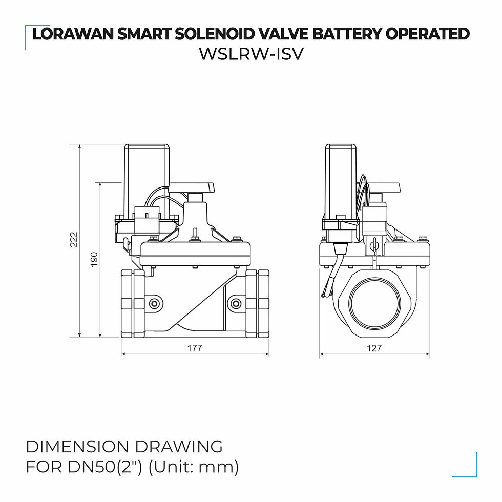
Please follow the checklist below for a successful installation:
1. Have you studied the dimensions of the device as above drawings?
2. Have you tested and make sure the device have been connected successfully as Section "1.7 Guide for Quick Test" above?
3. Have the device been configured properly as per Section 3.2 below?
4. Have the device been calibrated or validated as per Section 3.3 below?
5. Then you can start to install the device at site. Please check the following Installation Notes for Sensor Part (if available) before installation.
Installation Notes for Sensor Part (if available)
Installation of a latching solenoid valve requires precision, particularly regarding orientation and electrical pulses. Below are the essential notes for a successful setup.
1. Mechanical Mounting
Orientation: The best practice is to mount the valve with the solenoid coil facing upward (armature vertical). This prevents sediment from settling in the armature tube, which can jam the permanent magnet mechanism.
Flow Direction: Always check for the arrow or "IN" marking on the valve body. Installing it backwards will prevent the valve from sealing correctly, often causing it to leak even when "closed."
Filtration: Latching valves are highly sensitive to debris. Install a Y-strainer or filter upstream to protect the internal seals and plunger.
2. Electrical Wiring & Control
Polarity Check:
* 2-Wire: You must use an H-Bridge to flip the polarity. Check the datasheet for which color wire is positive for "Open."
Pulse Width: Set your controller to a pulse.
Warning: A pulse that is too long (continuous power) can overheat the coil or cause the plunger to "bounce" back out of its latched position.
Voltage Drop: Ensure your power supply can handle the peak current during the pulse. If using long wires, use a thicker gauge to prevent voltage drop, which could cause "weak latching."
3. Piping Best Practices
Support: Use a backup wrench on the valve body when tightening fittings. Never use the coil or armature tube as leverage, as this can bend the tube and cause the plunger to stick.
Sealing: Use 2–3 wraps of PTFE tape or pipe dope on NPT threads. Ensure no tape shreds enter the valve inlet, as even a tiny fragment can keep the valve from closing fully.
Expansion: In outdoor irrigation systems, allow for some pipe movement. If the pipe is pulled tight, it can stress the valve body and cause leaks.
4. Post-Installation Commissioning
Purge the Line: Before final connection, flush the pipes with water/air to remove metal shavings or debris.
Initial State Check: Latching valves can switch states during shipping due to vibrations. Manually pulse the valve "Closed" before turning on the main supply to avoid an accidental flood.
Pressure Test: Slowly increase system pressure. Check that the valve latches and unlatches under the actual working pressure (differential).
Installation Guide for Main Device
Check the Location for the best RF Signal
Make sure the site is good enough for RF signal transmission.
Tip: To maximize the transmission distance, the ideal condition is Line-of-sight (LOS) between the LoRaWAN sensor and the gateway. In real life, there may be no LOS condition. However, the LoRaWAN sensor still communicates with the gateway, but the distance will be reduced significantly.
DO NOT install the wireless sensor or its antenna inside a completed metallic box or housing because the RF signal can not pass through the metallic wall. The housing is made from Non-metallic materials like plastic, glass, wood, leather, concrete, and cement…is acceptable.
Install the Device on the Wall/Housing/Structure/valve body and connect to the external latching solenoid valve
Mount the sensor onto a wall/housing/structure with provided screws.

In some case, the controller is installed on the body of the external latching solenoid valve with provided U bracket

Connect the first wire (+ label) of the cable to (+) of external latching solenoid valve and connect the second wire (-label) of the cable to (-) of external latching solenoid valve. Below are example of connection to HUNTER solenoid valve and RAIN BIRD solenoid valve

Note:
Device batteries must be not available during installation and wiring.
1.9 Payload Document and Configuration Tables
Please click below button for:
-
Payload decoding of Uplink messages;
-
Payload encoding of Downlink messages;
-
Configuration Tables of device.
Note:
If the content of below web payload, memory map, and sample decoder could not be copied, please install the extension of "Enable Copy Paste - E.C.P" for Microsoft Edge and for Google Chrome.
1.10 How to connect device to Back-end/ Network Server/ Coordinator
Please find below the examples of adding Daviteq's LoRaWAN sensor to the following Network servers:
ThingPark Community (of Actility);
Things Stack (of The Things Network).
You can use the similar methods to add LoRaWAN sensors to other Network Server.
1. THINGPARK COMMUNITY (ACTILITY) NETWORK SERVER
1.1. Example to add the Tektelic LoraWAN gateway Model T0005204 to ThingPark Enterprise SaaS Community
1. Log in to your ThingPark Enterprise account via the link: https://community.thingpark.io/tpe/
2. Browse on the left panel to Base Stations, click the drop-down menu, then click Create.

3. Select the base station’s Tektelic.
※ If you do not find the Tektelic, click View More Manufacturers.

4. On the following screen, select the Model: Micro 8-channels from the drop-down list.

5. Fill the form as below table:
Input exactly as above Input field column, except Name field is user-defined and is different from the existing base station name on the network server.
After filling the registration form, click CREATE to complete adding the base station to the network server.
1.2. Add Daviteq's LoRaWAN devices to ThingPark Enterprise SaaS Community
ThingPark Enterprise supports all Classes of LoRaWAN® devices. By default, the sensor supports Over-the-Air Activation (OTAA) with a local Join Server that is programmed at the factory.
Manual provisioning of OTAA devices using a local Join Server. To learn more, see Activation modes.
1. At left panel of the screen of the Thingpark GUI, click Devices > Create from the dashboard.

2. Select the Generic supported by your device on your screen.

3. Select the Model of LoRanWAN 1.0.3 revA - class A with correct frequency plan

4. Fill the form as below table:
In addition to filling out the form, the option to select the connection between ThingPark and Daviteq application (Globiots).

After filling out the registration form, please click CREATE to add devices to the network server.
1.3. Send a downlink frame from Thingpark Network Server to the device
Follow the below steps to send the downlink frame from Thingpark Network Server to the device:
This functionality is active only when a connection is associated to the device (one of the color codes with a green bullet).
1. Navigate to the left panel, click the Devices' drop-down menu, then click List.

2. Browse the right side in the Devices, click the icon of the device and click Send Downlink.

3. Input the downlink code to the Payload field and input 1 to the Port field, and then click Validate.
The downlink data is added to the device downlink queue in network server. The downlink is sent after the network server receive an uplink from the device.

2. THINGS STACK (THE THINGS NETWORK) NETWORK SERVER
2.1. Add Sentrius LoraWAN gateway (Model RG19) to The things Stack network server
1. Log in to you’re The Things Stack account
2. Click the tab Gateways, click Add gateway button

3. Fill out the form as below table:
Input exactly as above Input column, except the Gateway Name field and the Gateway ID field is user-defined. It is different from the existing gateway name and gateway ID on the network server.
After filling the registration form, click Create gateway to complete adding the base station to the network server.

2.2. Add Daviteq's LoRaWAN device to The Things Stack network server
The Things Stack supports all Classes of LoRaWAN® devices. By default, the sensor supports Over-the-Air Activation (OTAA) with a local Join Server programmed at the factory.
1. Browse on the top panel, click the tab Application, and click Add application button to create an application

2. Fill in the information fields as user-defined, then select Create application

3. After the application is created successfully, select Add end device to register end device (LoRaWAN sensor)

4. Fill out the form as below table:
After filling out the registration form, please click the Register end device button to add the device to the network server.


2.3. Send a downlink frame from The Things Stack Network Server to the device
1. Select the device to send downlink
2. Input 1 to the FPort and input the downlink data in the payload field, and then tick Confirmed downlink and click Schedule downlink.

2
MAINTENANCE
2.1 Troubleshooting
Please find below steps to identify the problems from Communication Part or Sensor Part:
* If the device cannot connect to the Gateway or System or Co-ordinator at the first time, it is the Communication Problem;
* If the device status like battery, RSSI level, data status or other communication is normal, but the measured values are not updated or wrong, it would be the problems of Sensor part;
* If the data coming to gateway, system or co-ordinator is not frequently as expected, the problem would be Communication.
Please refer below the troubleshooting guide for Communication and Sensor Part.
Troubleshooting for Communication
Troubleshooting for Sensor Part (if available)
Troubleshooting a latching solenoid valve can be tricky because the failure could be magnetic, electrical, or mechanical. Unlike standard valves, a latching valve’s "off" state doesn't necessarily mean "power off"—it means a reverse pulse was sent.
1. Electrical Diagnostics
If the valve isn't switching, start by verifying the control signal:
Pulse Verification: Use a multimeter in "Min/Max" or "Peak" mode.
Resistance Test: Disconnect the wires and measure the coil's resistance (Ohms).
Polarity Check: If the valve opens but won't close, ensure your controller is actually reversing the voltage for the "Close" command. If using an H-bridge, check if one of the transistors has failed.
2. Mechanical & Fluid Issues
Even if the electronics are perfect, physical blockages or pressure issues can stop the latching action.
The "Click" Test: If you hear a click but no fluid flows (or stops), the plunger is moving, but the diaphragm or seal is stuck or torn.
Pressure Differential: Many latching valves are pilot-operated. If the system pressure is too low (e.g., a near-empty gravity tank), the valve won't have enough force to push the diaphragm into the "latched" open or closed position.
Debris & Contamination: Small particles (sand, rust, or PTFE tape) can jam the plunger. Because latching valves use a weak permanent magnet to hold position, even tiny friction from dirt can prevent it from "catching" the magnet.
3. Magnetic Failure
Plunger Bounce: If you apply a pulse that is too long or too high voltage, the plunger may hit the stop so hard that it bounces back out of the magnetic field before it can latch. Try shortening the pulse duration in your code.
Residual Magnetism: Over time, the metal plunger can become permanently magnetized in the wrong direction. If the valve refuses to unlatch, try a slightly longer "Close" pulse to fully neutralize the field.
Vibration: High-vibration environments can physically "shake" the plunger off the internal permanent magnet, causing the valve to close unexpectedly.
2.2 Maintenance
Maintenance for Main device
There is no requirement for maintenance of the Hardware of LoRaWAN latching solenoid valve Node For solenoid valve, please refer sensor/actuator part for information
Maintenance for Sensor part (if available)
Maintenance for a latching solenoid valve focuses on protecting the permanent magnet and the internal seals from debris. Because these valves are often used in remote or battery-powered locations, reliability is key.
1. Routine Inspection Schedule
Monthly Functional Test: Cycle the valve "Open" and "Close" at least once every 4 weeks. This prevents the plunger from sticking due to mineral buildup or "stiction" from long periods of inactivity.
Leak Check: Visually inspect connection points and the exhaust port for moisture, which indicates a failing internal seal or diaphragm.
Electrical Check: Inspect wire terminals for corrosion. In outdoor setups, ensure the drip loop is intact so water doesn't travel down the wires into the coil housing.
2. Internal Cleaning Procedure
If the valve becomes sluggish or leaks, it likely has internal debris.
De-pressurize: Shut off the fluid supply and disconnect power.
Disassemble: Unscrew the solenoid coil (usually a "jar-top" or held by 4 bolts). Carefully remove the plunger and spring.
Clean Components: Rinse the plunger, spring, and rubber diaphragm in clean water. Use a soft brush to remove grit.
Clear the Pilot Orifice: Use a thin, flexible wire to ensure the tiny "pilot" holes in the diaphragm or valve body are not clogged.
Remove Scale: For hard water buildup (calcium), soak non-electrical metal parts in a diluted vinegar solution.
3. Protective Measures
Upstream Filtration: Always install a Y-strainer or filter before the valve. This is the single most effective way to reduce maintenance.
Avoid Over-Tightening: When reassembling, tighten bonnet bolts or the coil by hand plus a quarter turn. Over-tightening can crack the housing or dent the armature tube, jamming the plunger.
Ventilation: While latching valves don't get hot during operation, ensure they aren't in a completely sealed, high-heat environment which can degrade the permanent magnet over years.
3
ADVANCED GUIDE
3.1 Principle of Operation
Principle of Operation for device WSLRW-ISV | FW1
Daviteq LoraWAN Latching Solenoid Valve comprises 02 parts linked internally:
• The Daviteq LoraWAN wireless transmitter;
• The Daviteq Smart Battery-Operated Solenoid Valve (ISV)
What are the primary output values?
• VALVE CONTROL COMMAND: Valve control command. This parameter equals VALVE_CONTROL_COMMAND in the uplink payload
• NRS COUNTER ON: Non-resettable counter values for the valve open command. This parameter equals NRS_COUNTER_ON in the uplink payload
• NRS TIMER ON: Non-resettable timer values for the valve open status, unit of second. This parameter equals NRS_TIMER_ON in the uplink payload
• VALVE CONTROL VOLTAGE: The power supply for the valve, unit of Volt. This parameter equals VALVE_CONTROL_VOLTAGE_X10 in the uplink payload divided by 10
• SCHEDULE CONTROL COMMAND: Schedule's control command: open valve/close valve/clear schedule queue. This parameter equals SCHEDULE_CONTROL_COMMAND in the uplink payload
• SCHEDULE START TIME: Schedule's start time for open valve/close valve, in format of epoch time since 1/1/2020 00:00:00 GMT+0. It represents the number of seconds that have elapsed since January 1, 2020 00:00:00 GMT+0. If SCHEDULE_START_TIME equals zero, the control command will be implemented immediately and the schedule will not be put into the sensor memory queue. This parameter equals SCHEDULE_START_TIME in the uplink payload
• SCHEDULE DURATION: Schedule's duration for open valve/close valve command, unit of second. If the duration equal zero, the command will be implemented until next control command. This parameter equals SCHEDULE_DURATION in the uplink payload
• SCHEDULE ORDINAL NUMBER: Schedule's ordinal number in the valve's memory queue. If the SCHEDULE_START_TIME equal 0, the SCHEDULE_ORGINAL_NUMBER will be equal zero. This parameter equals SCHEDULE_ORDINAL_NUMBER in the uplink payload
• TOTAL SCHEDULE: Total available schedules in the valve memory queue. This parameter equals TOTAL_SCHEDULE in the uplink payload
• SCHEDULE STATUS: Schedule implementation status (started, complete). This parameter equals SCHEDULE_STATUS in the uplink payload
What are the secondary output values?
Below output values are useful for device maintenance and troubleshooting.
• LRW NODE POWER LEVEL: Power supply level (battery or external power) for LoRaWAN node. This parameter equals LRW_NODE_POWER_LEVEL in the uplink payload
• Alarm: alarm status of the device. The parameter in the payload is ALERT_STATUS
• Sensor current configurations: current main settings of the sensor and this parameter in the payload is CURRENT_CONFIGURATION
• Sensor hardware version: hardware version of the sensor and this parameter in the payload is HW_VERSION
• Sensor firmware version: firmware version of the sensor and this parameter in the payload is FW_VERSION
• Valve type: Type of the valve body (2=Type B (Latching Solenoid Valve)). This parameter equals VALVE_TYPE in the uplink payload
• VALVE POWER LEVEL: Battery voltage level for the last valve open event of valve control. This parameter equals VALVE_POWER_LEVEL in the uplink payload
Principle of operation
For latching solenoid valve, when LoRaWAN valve node receives a command of ON valve, the valve node output the pulse with pulse width of CONTROL_PULSE_WIDTH millisecond and positive current to the external solenoid valve to open the valve. When LoRaWAN valve node receives a command of OFF valve, the valve node output the pulse with pulse width of CONTROL_PULSE_WIDTH millisecond and negative current to the external solenoid valve to close the valve.
Device power on / power reset/ reed switch operation
When the device is power on or power reset, the VALVE CONTROL COMMAND will equal DEFAULT_COMMAND. DEFAULT_COMMAND might have one of following values:
1: Command to open valve
2: Command to close valve (default value)
3: Last control command.
If the last control command is different from DEFAULT_COMMAND, the DEFAULT_COMMAND control command will be implemented and ALARM uplink message will be sent to Network Server after the control command implementation is completed. The result of control is ALERT_STATUS and might be one of following:
1: open valve command
2: close valve command
3: valve cable or connector error
4: duplicated control command (The current control command is the same as last control command)
Scheduled control
Principle of scheduled control
In addition to instant control functions, the new version of valve enables scheduled control that is configured in real time, allowing for up to 15 control commands to be stored in memory.
The necessary steps involve synchronizing the real-time clock for the valve and setting up control schedules. Configuring the real-time clock for the valve is set through Downlink type 5, and scheduled control commands for valve are set through Downlink type 2. These control commands will be stored in the valve’s memory and executed when the start time of a command matches the real-time.
Configure the Real-Time Clock
The device has its own real-time clock. The real-time clock only runs when the device is powered by batteries. The value of the real-time clock increases by 1 every second. The device schedule in device queue operate based on device real-time clock. When start time of the schedule in the queue equals to the value of device's real-time clock, the schedule's command will be implemented. If the device is disconnected from the batteries, the current real-time clock value will be stored in EEPROM. If the device is connected to batteries again, the device read the stored time clock value in the EEPROM, assign this value to real-time clock and the real-time clock start to run ( increase by 1 every second).
When device receives downlink to write the value to SYNC_E_TIME parameter/configuration/setting on the memory device, the device will write the time value in the downlink to the SYNC_E_TIME parameter as well as write this value to the device's real-time clock. The downlink for SYNC_E_TIME should be sent after the the device is power up OR/AND before the schedule's downlink is sent. SYNC_E_TIME value remains in the memory when the valve is disconnected from the battery
Use downlink type 5 to set the real-time clock on the valve. This step is crucial for ensuring that the valve operates according to the correct time. The Real-time clock is Synchronized time from network server, in format of Epoch time since 1/1/2020.
The synchronized time is equal difference in seconds between current time and original point (00:00:00 01/01/2020)
Example: the current time is 12:00:00 29-04-2024 so the synchronized time is 136555200 (Decimal) = 0823AAC0 (Hex)
Free online tool to calculate the difference between two dates:
https://www.epochconverter.com/date-difference
Use downlink type 5 to write synchronized time to parameter SYNC_E_TIME of valve.
Here is the format of downlink type 5:

Example: the current time is 12:00:00 29-04-2024 so the synchronized time is 136555200 (Decimal) = 0823AAC0 (Hex)
The final downlink payload of example is 63040823AAC00005
Note:
• The real-time clock may run inaccurately when the valve loses power from its battery. Therefore, we recommend periodically synchronizing the real-time clock, ideally before scheduling control commands for the valve.
• According to the principles of LoRaWAN network, the valve will received a downlink message after it sends an uplink message. Therefore, it’s necessary to determine the timing of when the valve sends an uplink message in order to calculate the synchronized time accurately. For example, if you intend to send a downlink to synchronize the time at 9:30, but according to the cycle, the valve only sends an uplink at 10:00, then you must use the synchronized time at 10:00 to calculate synchronized time in downlink.
Set Up Control Commands
Use downlink type 2 to send control commands to the valve. These commands include the specific parameters you want the valve to perform. Here is the format of Downlink type 2

SCHEDULE_START_TIME (0-4294967296):
Schedule's start time for SCHEDULE_CONTROL_COMMAND, in format of epoch time since 1/1/2020 00:00:00 GMT+0. It represents the number of seconds that have elapsed since January 1, 2020 00:00:00 GMT+0. If SCHEDULE_START_TIME equal zero, the control command will be implemented immediately and the schedule will not be put into the sensor memory queue. The synchronized time in downlink from the network server must be also in the same format as one of SCHEDULE_START_TIME.
- SCHEDULE_DURATION (0-65536):
Schedule's duration for open valve/close valve command, unit of second. If the duration equal zero, the command will be implemented until next control command.
- Reserved: Reserved for future usage
- SCHEDULE_CONTROL_COMMAND (1: open valve ; 2: close valve; 3: clear all schedule in queue)
Schedule's control command: open valve/close valve/clear schedule queue.
Example 1:
Create a schedule control command to open the valve at 11:30:00 on April 29, 2024, then close the valve after 60 minutes.
SCHEDULE_START_TIME = 136553400 (DEC) = 0823A3B8
SCHEDULE_DURATION = 3600(DEC)= 0E10 (HEX)
Reserved: 00 (HEX)
SCHEDULE_CONTROL_COMMAND = 1
DOWNLINK_TYPE = 2
FINAL DOWNLINK : 0823A3B80E100012
Example 2:
Create a schedule control command to open the valve immediately upon receiving the downlink, then close the valve after 30 minutes.
SCHEDULE_START_TIME = 00000000 (DEC) = 00000000 (HEX)
SCHEDULE_DURATION = 1800(DEC)= 0708 (HEX)
Reserved: 00 (HEX)
SCHEDULE_CONTROL_COMMAND = 1
DOWNLINK_TYPE = 2
FINAL DOWNLINK : 0000000007080012
Example 3:
Create a control command to open the valve at 13:00:00 on April 29, 2024, then keep it open until the next control command.
SCHEDULE_START_TIME = 136558800 (DEC) = 0823B8D0 (HEX)
SCHEDULE_DURATION = 0000(DEC)= 0000 (HEX)
Reserved: 00 (HEX)
SCHEDULE_CONTROL_COMMAND = 1
DOWNLINK_TYPE = 2
FINAL DOWNLINK : 0823B8D000000012
Example 4:
Create a downlink to clear all schedule commands in valve’s memory
SCHEDULE_START_TIME = 00000000 (DEC) = 00000000 (HEX)
SCHEDULE_DURATION = 0000(DEC)= 0000 (HEX)
Reserved: 00 (HEX)
SCHEDULE_CONTROL_COMMAND = 3
DOWNLINK_TYPE = 2
FINAL DOWNLINK : 0000000000000032
Example 5:
Create a control command to open the valve immediately upon receiving the downlink, then keep it open until the next control command.
SCHEDULE_START_TIME = 00000000 (DEC) = 00000000 (HEX)
SCHEDULE_DURATION = 0000(DEC)= 0000 (HEX)
Reserved: 00 (HEX)
SCHEDULE_CONTROL_COMMAND = 1
DOWNLINK_TYPE = 2
FINAL DOWNLINK : 0000000000000012
Example 6:
Create a control command to close the valve immediately upon receiving the downlink, then keep it close until the next control command.
SCHEDULE_START_TIME = 00000000 (DEC) = 00000000 (HEX)
SCHEDULE_DURATION = 0000(DEC)= 0000 (HEX)
Reserved: 00 (HEX)
SCHEDULE_CONTROL_COMMAND = 2
DOWNLINK_TYPE = 2
FINAL DOWNLINK : 0000000000000022
Note:
• The schedule control commands will be stored in the memory of the valve and executed in chronological order base on the SCHEDULE_START_TIME.
• The maximum number of schedule control commands is 15. If the number of commands exceeds 15, the valve will automatically delete the earliest commands and overwrite them with new ones.
• Two schedules are defined as duplicate if their start times are the same. When a schedule duplicate with another schedule in memory, the latter schedule will overwrite the former one
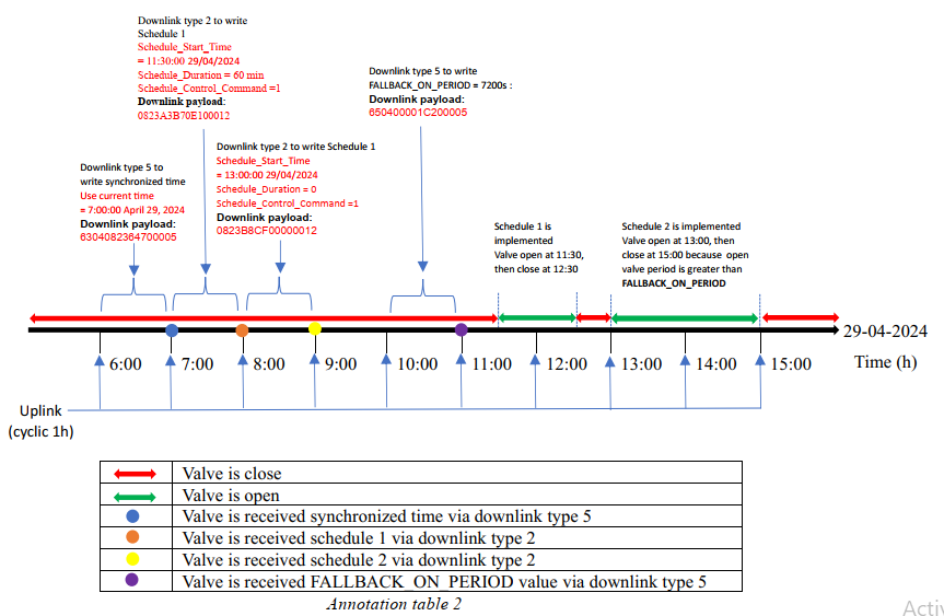
Example of Multi-scheduled Control
*Default configuration:
➢ The valve is configured with an uplink transmission cycle of 1 hour, and
uplinks are sent precisely at even hours.
➢ The default state of the valve is closed.
*Demand: To configure the valve to automatically open twice:
➢ The first opening will be from 11:30 to 12:30 on April 29, 2024.
➢ The second opening will be from 14:00 to 14:30 on April 29, 2024.

Note:
The period between downlinks must be equal OR greater than cyclic period to ensure all downlinks will be received by the valve
The downlink process need strong LoRaWAN signals than uplink process
Fallback control
Principle of Fall-back control
With this function, we can limit the maximum opening time or the maximum closing time of the valve. Here are two parameters that can be set for this function:
• FALLBACK_ON_PERIOD
Maximum allowable period for open valve, unit of second. If the open valve period is greater than FALLBACK_ON_PERIOD, the valve will be closed automatically and the alarm event will occur. If FALLBACK_ON_PERIOD =0, no fallback function for open valve is available
• FALLBACK_OFF_PERIOD
Maximum allowable period for close valve, unit of second. If the close valve period is greater than FALLBACK_OFF_PERIOD, the valve will be opened automatically and the alarm event will occur.
If FALLBACK_OFF_PERIOD =0, no fallback function for close valve is available
Use downlink type 5 to set FALLBACK_ON_PERIOD or FALLBACK_OFF_PERIOD.
Here is an example of downlink for Fallback function.
FALLBACK_ON_PERIOD = 7200s (DEC) = 00001C20 (HEX)
FALLBACK_OFF_PERIOD = 3600s (DEC) = 00000E10 (HEX)

Example of Fall-back control
• Default configuration:
➢ The valve is configured with an uplink transmission cycle of 1 hour, and uplinks are sent precisely at even hours.
➢ The default state of the valve is closed.
• Demand: To configure the valve to automatically open twice:
➢ The first opening will be from 11:30 to 12:30 on April 29, 2024.
➢ The second opening will be at 14:00 at April 29, 2024, then keep it open until the next control command
➢ The valve only allows a maximum opening time of 2 hours (FALLBACK_ON_PERIOD = 7200s)
LED indication
There is only a LED on the housing to show both sent uplinks and latest control statuses.
The color of the LED is based on uplink type. Refer the PAYLOAD AND MEMORY MAP DOCUMENT for LED color of each uplink type. In addition, this LED also blinks white color for latest OPEN valve control command and purple color for latest CLOSE valve control command
Configuration for LATCHING SOLENOID VALVE CONTROLLER
For LATCHING SOLENOID VALVE type with primary battery, the configurations must be:
VALVE_TYPE_CODE = 2: Type B (Latching Solenoid Valve)
Class mode = 0: End-Device Class of class A
Note:
If the region are US915, IN865 or AU915, the RF is fixed to SF7 and ADR (Adaptive Data Rate) is fixed to OFF.
Principle of Operation of Sensor part (if available)
A latching solenoid valve (also known as a bi-stable or pulse valve) differs from a standard solenoid valve by its ability to maintain its position (open or closed) without a constant supply of electricity. It effectively "remembers" its last state.
1. The Core Components
The primary difference in construction is the addition of a permanent magnet or the use of residual magnetism.
Solenoid Coil: A standard copper winding.
Permanent Magnet: Usually located at the top of the armature stroke.
Plunger/Armature: The moving core that controls fluid flow.
Spring: A return spring that exerts force in the opposite direction of the magnet.
2. The Operating Principle
The operation relies on a balance of forces between the electromagnet, the permanent magnet, and the mechanical spring.
To Open (The Latch)
Electrical Pulse: A short DC pulse (typically 20–50 millisecond) is sent through the coil.
Magnetic Boost: The coil generates an electromagnetic field that reinforces the permanent magnet's field.
Actuation: This combined force is strong enough to overcome the spring and pull the plunger up.
Latching: Once the plunger is at the top, it is close enough to the permanent magnet to be held there by the permanent magnet's field alone. The power can now be cut, and the valve stays open.
To Close (The Unlatch/Release)
Reverse Pulse: A short DC pulse of opposite polarity is sent through the coil.
Magnetic Cancellation: The reverse field opposes and cancels out the permanent magnet’s field.
De-latching: With the magnetic "glue" gone, the internal spring pushes the plunger back down to the seat.
Holding: The valve remains closed until another positive pulse is received.
3. Key Advantages
Because these valves only require energy for a fraction of a second during switching, they offer unique benefits:
Zero Heat Rise: Since the coil isn't "on" most of the time, it doesn't get hot. This is critical for temperature-sensitive fluids like blood or chemicals.
Battery Efficiency: Ideal for remote irrigation or portable medical devices where power is limited.
Failsafe Behavior: Unlike standard valves that return to a "default" state if power fails, a latching valve stays in its current state during a blackout.
Default Configuration Parameters of Sensor part (if available)
The ISV has the default configuration, however, those parameters can be changed. The user can change the configuration on the wireless transmitter so that the complete sensor (transducer + wireless) delivers the proper output value. Please check the Payload document for more information.
3.2 Configuration
How to configure the device?
Sensor configuration can be configured in 02 methods:
Method 1: Configuring via Downlink messages, port 1 (default).
Method 2: Configuring via Offline cable.
Step to access configuration port: Open housing by turning counter-clockwise 2 screws, then remove the anti-interference shield, the configuration port as below figure:

Note: The sensor is only active for offline configuration in the first 60 since power up
Which Parameters are configured?
Please check Part G in Section 1.9 Payload Documents above.
Please check the Part D & E in Section 1.9 Payload Documents above.
Method 1: Configuration via Downlink messages
Method 2: Configuration by Offline Cable
Please download the Configuration Template File of this sensor to be used in Step 4 below.
Instructions for offline configuration of the Daviteq LoRaWAN sensors. Please follow the following steps.
Note: The sensor is only active for offline configuration in the first 60 since power up by battery or plugging the configuration cable.
1. Prepare equipment and tools
The following items must be prepared for configuration.
A PC using the Windows OS (Windows 7 or above versions). The PC installed the COM port driver of the Modbus configuration cable (if needed). The driver is at link: Modbus Configuration Cable COM port driver for PC and the instruction to install the driver at link: How to install the driver.
A Modbus configuration cable
Tools to open the plastic housing of LoRaWAN sensors (L hex key or screwdriver)
2. Download and launch Daviteq Modbus configuration software
Click the link below to download Daviteq Modbus configuration software:
https://filerun.daviteq.com/wl/?id=yDOjE5d6kqFlGNVVlMdFg19Aad6aw0Hs
After downloading the software, unzip the file named: Daviteq Modbus Configuration.zip and then copy the extracted folder to the storage drive for long-term use.
Open the folder, double click on the file Daviteq Modbus Configuration Tool Version.exe to launch the software and the software interface as below:

Note: The software only runs on Microsoft Windows OS (Windows 7 and above).
3. Connect the cable and configure the sensor
Step 1:
Connect the PC to the sensor using the configuration cable.
- Use the configuration cable (Item code: TTL-LRW-USB-01).

- Connect the USB-A plug into the USB-A socket of the PC.

Step 2:
On the configuration software, choose the relevant Port (the USB port which is the cable plugged in) and set the BaudRate: 9600, Parity: none
Step 3:
Click Connect button to connect the software to the sensor. After successful connection, the Connected status will show on the software.

Step 4:
Import the configuration template file of the sensor (as above link) to the software: click menu File/ Import New and then browse the relevant sensor template file (csv file) and click Open to import the template file.
Note: The sensor is only active for configuration for 60 seconds since plugging the configuration cable or the power supply into the sensor.
Each sensor type has its own template file. Refer to the sensor's manual to download the correct file.
Step 5:
Open the housing of the sensor and quickly plug the connector of the configuration cable into sensor's modbus configuration port as below figure. After plugging the connector, the software will read the parameter values automatically.

Plug the cable connector into sensor's modbus configuration port. This port is located at a different location, depends on the sensor type
Note: If the sensor has SKU of WSLRWEX-PPS and hardware version 1 & 2, the sensor must be powered by batteries for configuration
Step 6:
Read the current value of the parameter with Modbus Function 3
At the relevant row of the parameter, check box 3 on column Func to read the value of the parameter. The read value is shown in VALUE ON MEMMAP column.

The sensor is only active for configuration for 60 seconds since plugging the configuration cable or the power supply into the sensor. After 60 seconds, the TIME_OUT text will show on EXCEPTION column of the software.
Step 7:
Write the new setting to the parameter with Modbus Function 16
Double click on the column VALUE TO WRITE of the parameter and input the new setting value of the parameter;
Uncheck the tick on the FC column of the parameter, click on the arrow, select 16 and then check on the FC column to write a new setting to the parameter. The WRITE_OK text will show on EXCEPTION column if the software successfully writes the setting.

Repeat Step 6 to read the setting of the parameter for double-checking.
Note: For some critical parameters of the sensor, the password in "password for setting" must be written before writing the new settings to these parameters.
Only read/ write registers are allowed to write.
The sensor is only active for configuration for 60 seconds since plugging the configuration cable or the power supply into the sensor. After 60 seconds, the TIME_OUT text will show on EXCEPTION column of the software.
4. Troubleshooting
3.3 Calibration/ Validation
How to force sensor to send data for calibration/ validation (if available)
Using the magnet key, the device can be triggered to send data to the gateway immediately.

Note:
Upon transmitting the data to the gateway using the magnetic key, the timer for the transmission time interval will be reset.
The minimum time interval between two manual triggers is 15 seconds. If the interval is less than 15 seconds, data transmission will not occur.

Calibration/ Validation sensor (if available)
"Calibration" for a latching solenoid valve usually refers to one of two things: Electrical Calibration (tuning the control signal to ensure reliable switching) or Flow Calibration (correlating the open-time to the volume of fluid delivered).
Unlike standard valves, a latching valve is binary; it is either "latched" or "released," so you aren't calibrating a middle position, but rather the reliability of the transition.
1. Electrical "Pulse" Calibration
Since latching valves only move when they receive a pulse, you must calibrate the Pulse Width and Voltage to ensure the plunger moves but doesn't bounce back.
Pulse Width (Duration): Most valves require a pulse between 20ms and 50ms.
Too short: The plunger won't reach the permanent magnet (won't latch).
Too long: You waste battery and, in some cases, the plunger can "bounce" off the stop and fail to latch.
Voltage Threshold: Check the minimum "Pull-in" voltage. If you are using a battery, calibrate your low-voltage cutoff to ensure the pulse still has enough energy to overcome the spring.
Polarity Check: Ensure your "Close" pulse is exactly the reverse of your "Open" pulse. If using an H-bridge controller, calibrate the timing so there is a "dead time" (a few milliseconds of zero voltage) between state changes to prevent short circuits.
2. Flow & Volume Calibration
If you are using the valve for precise dosing (like in irrigation or lab rewards), you must calibrate the relationship between Time and Volume.
The Two-Point Test: Measure the weight/volume of liquid dispensed at two different intervals (e.g., a 20ms pulse vs. a 50ms pulse).
Establish a Baseline: Because there is a mechanical delay for the plunger to lift, the flow isn't perfectly instant.
Calculation: Use a linear equation to account for the "dead time" Td:
V = R * (Topen - Td )
V = Volume dispensed
R = Flow rate
Topen = Total time the valve is held open
Td = The delay time it takes for the valve to physically open after the pulse starts.
3. Mechanical Verification (Troubleshooting)
If the valve isn't latching correctly during calibration, check these mechanical factors:
Pressure Differential: Many latching valves are "pilot-operated" and require a minimum pressure to stay latched. If you calibrate it on a workbench with no water/air pressure, it may fail to stay open.
Residual Magnetism: Over thousands of cycles, the plunger can become slightly magnetized. If the valve "sticks" and won't release even with a reverse pulse, you may need to degauss the plunger or replace the internal spring.
4
PRODUCT SPECIFICATIONS
4.1 Specifications
Spec
5
WARRANTY & SUPPORT
5.1 Warranty
Warranty
Below terms and conditions are applied for products manufactured and supplied by Daviteq Technologies Inc.
Free Warranty Conditions
The manufacturer undertakes to guarantee within 12 months from shipment date.
Product failed due to defects in material or workmanship.
Serial number, label, warranty stamp remains intact (not purged, detected, edited, scraped, tore, blurry, spotty, or pasted on top by certain items).
During the warranty period, if any problem of damage occurs due to technical manufacturing, please notify our Support Center for free warranty consultancy. Unauthorized treatments and modifications are not allowed.
Product failed due to the defects from the manufacturer, depending on the actual situation, Daviteq will consider replacement or repairs.
Note: One way shipping cost to the Return center shall be paid by Customers.
Paid Warranty
The warranty period has expired.
The product is not manufactured by Daviteq.
Product failed due to damage caused by disasters such as fire, flood, lightning or explosion, etc.
Product damaged during shipment.
Product damaged due to faulty installation, usage, or power supply.
Product damage caused by the customer.
Product rusted, stained by effects of the environment or due to vandalism, liquid (acids, chemicals, etc.)
Product damage is caused by unauthorized treatments and modifications.
Note: Customers will be subjected to all repairing expenses and 2-way shipping costs. If arises disagreement with the company's determining faults, both parties will have a third party inspection appraise such damage and its decision be and is the final decision.
5.2 Support
Support via Help center
If you need our support for Daviteq device's installation, configuration, test, and decode, please input support request at link: https://forms.office.com/r/XWHbYG7yy7
Our support engineer will contact you via email or the support ticket system.
If you have any questions about the product, you can search for information on our web (https://www.iot.daviteq.com/). If you can't find the right information, please register an account and send us a request at link Contact us | Daviteq Technologies . We will respond within 24 hours.