
Only available for Logged-in member. Please login or register to access this information.Or use the Temporary User that we have provided to you via email.
expiry time

Item codes | FW Released Date | Changes Information |
|---|---|---|
WSLRWEX-PID-01 | 22/12/2023 | Initial version |
1
QUICK INSTALLATION GUIDE
1.1 Introduction
WSLRWEX-PID is a LoRaWAN sensor with Ex d explosion-proof approval and comes with a built-in high-performance PID (photoionisation detectors) technology sensor to detect the Volatile Organic Compounds (VOCs) and Hydrocarbon Gases in the air. It comes with Local LCD display, multi-colored status display, and magnet buttons for easy operation at field, without the need of turn off power and hot work permit. With 10.6 eV lamp allowing the instrument to detect a wide range of VOC gases whereas the TAC version utilises a 10.0 eV lamp to detect Total Aromatic Compounds (TACs), which helps focus on benzene. For LoRaWAN connectivity, it supports global frequency bands EU868, IN865, RU864, KR920, AS923, AS923-2, AU915, US915. The sensor can work perfectly with any LoRaWAN Gateway on the market. The PID gas sensor are ideal for detecting VOCs and TACs in areas such as refineries and petrol chemical facilities.
How the sensor connect to system?

System components:
The end nodes are LoRaWAN Sensors or Actuators;
The Gateways are LoRaWAN Gateway or Base Station;
The Network Server can be SAAS or On-premise server;
The Application Server is the destination software users want to utilize the data from/ to LoRaWAN sensors/ actuators.
How to set up the LoRaWAN system? Please follow these steps:
Adding the Gateways to a Network server. Please refer to the manual of Gateway and Network Server software;
Adding the End nodes to the Network Server;
Configure the callback or data forwarding from the Network Server to the Application Software by MQTT or HTTPS. Please refer to the manual of the Network Server.
Once the payload is on the Application server, decode data from Payload. Please check Section 1.9 for the Payload document.
1.2 Application Notes
For Applications
Gas Leakage Detection, Ambient Air Quality Monitor, Indoor Air Quality Monitor, Gas Analyzing, Warehouse Monitoring
Notes
Diffusion holes of the Sensor should be protected against the ingress of sprayed liquid or waterdrops.
The Sensor is NOT intended to Measure the target gas concentration contained in fluids.
1.3 When does device send Uplink messages?
The device will send uplink messages in the following cases:
Case 1: After power-up in the 60s, the device will send the first message called START_UP. The payload will tell the user the HW version, FW version, and current configuration of the device;
Case 2: Then, in every interval time (pre-configured), for example, 10 minutes, it will send the message called CYCLIC_DATA. The payload will tell the user the following data like measured values, battery level, and alarm status...
To change the cycle of data sending, you can change the value of the parameter: CYCLIC_DATA_PERIOD.
Case 3: If ALARM_ENABLED=1, the device will send ALARM message immediately when device switches from Normal state to Alarm state. It will repeat sending ALARM messages in predefined ALARM_PERIOD time interval (default is 10 minutes) if the Alarm state still exist;
Case 4: During the commissioning, testing, or calibration sensor, the user can force the device to send the uplink message to get the data immediately. This message is called FORCE_DATA. The payload will provide data like raw measured value, scaled measured values, battery level, and alarm status... It can be forced by applying the magnet key on the reed switch (under down arrow icon on screen) in 1s;
Case 5: If users want to change the configuration immediately, they don't need to wait until the next cyclic data-sending message; instead, they can force the device to send a special uplink message so that the device can get the new downlink message. This uplink message is named PARAMETERS_UPDATE. It can be forced by applying the magnet key (under down arrow icon on screen) in more than 5s.
Case 6: In every interval time (pre-configured), for example, 24 hours, it will send the message called HEARTBEAT. The payload will tell the user the following data like hardware version, firmware version, current sensor configuration
Case 7: If LNS_CHECK_MODE =1, it will send the confirmed uplink message called LNS_CHECK every 24 hours. This confirmed uplink message is a message where a LoRaWAN device is requesting a LoRaWAN network to confirm the reception of its message. If the device receives no confirmation message from LoraWAN network server, it will re-send the LNS_CHECK message every hour during 3 hours. After 4th hour, if the device still receives no confirmation messsage, it will reset itself to join the network server. The LNS_CHECK payload will tell the user the following data like hardware version, firmware version, current sensor configuration.
1.4 Default Configuration
This PID gas sensor module has the default configuration, however, those parameters can be changed. The user could change the configuration on the wireless transmitter so that the complete sensor (transducer + wireless) delivers the proper output value.
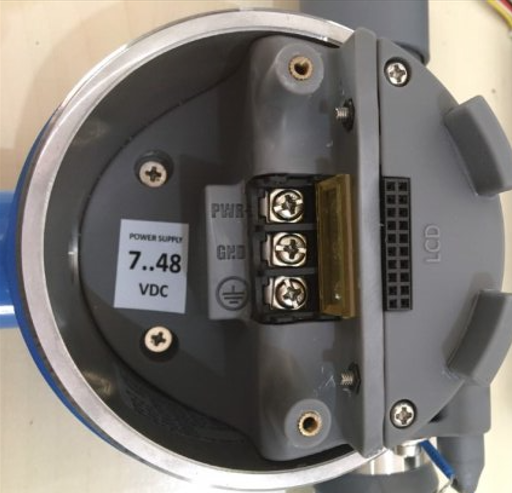
1.5 Battery/ Power Supply
12∼35VDC, max 200mA by external DC supply or Ex approved Solar Power Skid
1.6 What's in the Package?

1.7 Guide for Quick Test
With the default configuration, the device can be connected quickly to the Network Server by the following steps.
Step 1: Prepare the values of communication settings
Frequency zone: Most of the sensor was configured the frequency zone to suit customer application before delivery
DevEUI: Get the DevEUI on the product nameplate
AppEUI Default value: 010203040506070809
AppKey Default value: 0102030405060708090A0B0C0D0E0F10
Activation Mode: OTAA with local join server
Network Mode: Public
LoraWAN Protocol: version1.0.3
Class: A for sensor; C for actuator
If current basic common settings do not match with your region, network server/application, follow below instruction to change them as below:
NOTE: If the settings in above table are changed via downlink, the device MUST be reset to make the changed settings take effect. The reset is hard reset (Turn OFF external power supply, wait 3-7 minutes, and then turn ON external power supply OR take out battery, wait 3-7 minutes and then insert battery back ) OR soft reset via downlink 0. Downlink 0 hexadecimal value to reset device equal CURRENT_CONFIGURATION hexadecimal value in uplink but change the 15th value of the CURRENT_CONFIGURATION from 0 to A. For example, CURRENT_CONFIGURATION is 00C80064000B6000, the downlink 0 value for resetting device will be 00C80064000B60A0
For changing other settings, please refer to Section 3.2 Sensor configuration to change the other settings
Step 2: Register the device on the LoRaWAN network server
Input the above settings on your device registration page of the network server.
Note: Different network server software will have different device registration processes. Please refer to the manual of the network server software used for more details.
Please visit the below Section 1.10 to get the instructions for adding the LoRaWAN sensors to some common network servers such as Actility, TTN...
Step 3: Install the batteries to the device OR do power wiring and supply external power to the device if applicable
Please refer to Section 1.5 as above for instructions on battery installation OR for instructions to do power wiring and supply external power to the the device if applicable
After installing the battery in 60 seconds, the first data packet will be sent to the LoRaWAN gateway. After receiving the first data packet, the time of another packet depends on the value of the parameter: cycle_send_data. Additionally, you can use a magnet key to touch the magnetic switch point on the housing within 1 second to initiate force packet of the device to send data instantly and the LEDs on the housing will be lit with SKY BLUE color.
Step 4: Decode the payload of receiving package
Please refer to Section 1.9 Payload Document and Configuration Tables for details of decoding the receiving packet to get the measured values.
If the device has local display, measured values are shown on the local display
1.8 Installation
Dimension Drawings and Installation Gallery (Photos and Videos)

Please follow the checklist below for a successful installation:
1. Have you studied the dimensions of the device as above drawings?
2. Have you tested and make sure the device have been connected successfully as Section "1.7 Guide for Quick Test" above?
3. Have the device been configured properly as per Section 3.2 below?
4. Have the device been calibrated or validated as per Section 3.3 below?
5. Then you can start to install the device at site. Please check the following Installation Notes for Sensor Part (if available) before installation.
Installation Notes for Sensor Part (if available)
If the PID is deployed in a wall-mountable detector, the sensor is ideally located in the instrument to be as far from the wall mountings as possible, to minimize condensation phenomena caused by the air vs wall temperature disparity (consider the accumulation of particulates and heavy volatiles on shelves and kitchen units).
The sensor should be pointing downwards or sideways, to avoid slow accumulation of volatile in the sensor cavity, and dust.
Installation Guide for Main Device
Note: Do not open the device during installation at site (hazardous area Zone 0, 1, 2)
Check Location for the best RF Signal
Make sure the site is good enough for RF signal transmission.
Tip: To maximize the transmission distance, the ideal condition is Line-of-sight (LOS) between the sensor and the Gateway. In real life, there may be no LOS condition. However, the sensor still communicates with the Gateway, but the distance will be reduced significantly.
DO NOT install the wireless sensor or its antenna inside a completed metallic box or housing because the RF signal can not pass through the metallic wall. The housing is made from Non-metallic materials like plastic, glass, wood, leather, concrete, and cement…is acceptable.
Mounting
Use U bolt and DIN rail (provided in the product package) to mount the sensor into the holes as below pictures:


Wiring
Please follow instructions in below video for device wiring of power supply.
1.9 Payload Document and Configuration Tables
Please click below button for:
-
Payload decoding of Uplink messages;
-
Payload encoding of Downlink messages;
-
Configuration Tables of device.
Note:
If the content of below web payload, memory map, and sample decoder could not be copied, please install the extension of "Enable Copy Paste - E.C.P" for Microsoft Edge and for Google Chrome.
1.10 How to connect device to Back-end/ Network Server/ Coordinator
Please find below the examples of adding Daviteq's LoRaWAN sensor to the following Network servers:
ThingPark Community (of Actility);
Things Stack (of The Things Network).
You can use the similar methods to add LoRaWAN sensors to other Network Server.
1. THINGPARK COMMUNITY (ACTILITY) NETWORK SERVER
1.1. Example to add the Tektelic LoraWAN gateway Model T0005204 to ThingPark Enterprise SaaS Community
1. Log in to your ThingPark Enterprise account via the link: https://community.thingpark.io/tpe/
2. Browse on the left panel to Base Stations, click the drop-down menu, then click Create.

3. Select the base station’s Tektelic.
※ If you do not find the Tektelic, click View More Manufacturers.

4. On the following screen, select the Model: Micro 8-channels from the drop-down list.

5. Fill the form as below table:
Input exactly as above Input field column, except Name field is user-defined and is different from the existing base station name on the network server.
After filling the registration form, click CREATE to complete adding the base station to the network server.
1.2. Add Daviteq's LoRaWAN devices to ThingPark Enterprise SaaS Community
ThingPark Enterprise supports all Classes of LoRaWAN® devices. By default, the sensor supports Over-the-Air Activation (OTAA) with a local Join Server that is programmed at the factory.
Manual provisioning of OTAA devices using a local Join Server. To learn more, see Activation modes.
1. At left panel of the screen of the Thingpark GUI, click Devices > Create from the dashboard.

2. Select the Generic supported by your device on your screen.

3. Select the Model of LoRanWAN 1.0.3 revA - class A with correct frequency plan

4. Fill the form as below table:
In addition to filling out the form, the option to select the connection between ThingPark and Daviteq application (Globiots).

After filling out the registration form, please click CREATE to add devices to the network server.
1.3. Send a downlink frame from Thingpark Network Server to the device
Follow the below steps to send the downlink frame from Thingpark Network Server to the device:
This functionality is active only when a connection is associated to the device (one of the color codes with a green bullet).
1. Navigate to the left panel, click the Devices' drop-down menu, then click List.

2. Browse the right side in the Devices, click the icon of the device and click Send Downlink.

3. Input the downlink code to the Payload field and input 1 to the Port field, and then click Validate.
The downlink data is added to the device downlink queue in network server. The downlink is sent after the network server receive an uplink from the device.

2. THINGS STACK (THE THINGS NETWORK) NETWORK SERVER
2.1. Add Sentrius LoraWAN gateway (Model RG19) to The things Stack network server
1. Log in to you’re The Things Stack account
2. Click the tab Gateways, click Add gateway button

3. Fill out the form as below table:
Input exactly as above Input column, except the Gateway Name field and the Gateway ID field is user-defined. It is different from the existing gateway name and gateway ID on the network server.
After filling the registration form, click Create gateway to complete adding the base station to the network server.

2.2. Add Daviteq's LoRaWAN device to The Things Stack network server
The Things Stack supports all Classes of LoRaWAN® devices. By default, the sensor supports Over-the-Air Activation (OTAA) with a local Join Server programmed at the factory.
1. Browse on the top panel, click the tab Application, and click Add application button to create an application

2. Fill in the information fields as user-defined, then select Create application

3. After the application is created successfully, select Add end device to register end device (LoRaWAN sensor)

4. Fill out the form as below table:
After filling out the registration form, please click the Register end device button to add the device to the network server.


2.3. Send a downlink frame from The Things Stack Network Server to the device
1. Select the device to send downlink
2. Input 1 to the FPort and input the downlink data in the payload field, and then tick Confirmed downlink and click Schedule downlink.

2
MAINTENANCE
2.1 Troubleshooting
Please find below steps to identify the problems from Communication Part or Sensor Part:
* If the device cannot connect to the Gateway or System or Co-ordinator at the first time, it is the Communication Problem;
* If the device status like battery, RSSI level, data status or other communication is normal, but the measured values are not updated or wrong, it would be the problems of Sensor part;
* If the data coming to gateway, system or co-ordinator is not frequently as expected, the problem would be Communication.
Please refer below the troubleshooting guide for Communication and Sensor Part.
Troubleshooting for Communication
Troubleshooting for Sensor Part (if available)
2.2 Maintenance
Maintenance for Main device
There is no requirement for maintenance of the hardware of LoRaWAN device
Maintenance for Sensor part (if available)
In a fixed instrument, typically this will be every one to two months of cumulative sensor operation. However, when first deploying a PID instrument in a new environment, end users should be encouraged to bump test and re-calibrate as necessary.
Routine Maintenance
The electronics in the PID sensor are not accessible and designed to be maintenance-free.
The electrode stack is easily replaced and inexpensive. The PID stack will operate for years in most non-corrosive environments. It is recommended that end users of instruments containing PID carry at least one electrode stack in stock. The electrode stack is not toxic. Due procedures should be considered for safe disposal in the event of the stack being exposed to toxic environments.
Unscheduled Maintenance
The sensor have some error code for maintenance indicator for unscheduled maintanance as below table:

The PID should be dismantled and stack and lamp inspected in the following circumstances:
On exposure of the sensor to very humid, acidic (sour) and salty environments. This may cause inorganic salts to accumulate on PID enclosure walls, which ultimately compromises the screening potential of the PID fence electrode. This is often indicated by a moisture sensitive signal.
Visual indications of liquid ingress into the electrode stack.
A sensor error 4 indicates a failure of contact has developed between the sensor pins and the stack pads. The wings on the PID stack may fail after repeated dis- and re-assembly. It may also be caused by failure of the stack to engage fully with the sensor body, which may be corrected by refitting the lamp and stack. The PID lamp should be cleaned and replaced as necessary if the responsivity of the sensor, as measured in bump tests or during calibration, decreases unexpectedly. Note that exposure of the sensor to amines is liable to temporarily contaminate the PID lamp. Instrument design should cater for this.

Removing the electrode stack and lamp
CAUTION:
Only use the electrode stack removal tool. Any other tools (for example screwdrivers) may damage your PID body and will invalidate your warranty.
Wear gloves. Carefully remove the sensor from instrumentation.
Locate electrode stack removal tool in the side slots of the PID and squeeze together until electrode stack and lamp are released.
Lift carefully the PID body away from the electrode stack and lamp.
Occasionally the lamp may be temporarily lodged in the sensor body and will need to be freed carefully with tweezers. Occasionally the small spring behind the lamp will come out when the lamp is removed from the sensor. Simply replace it into the sensor body.

Inspecting the PID stack
On removal of the electrode stack, carefully inspect the underside. The visible electrodes should be shiny and metallic. If there are any signs of corrosion or water ingress the stack should be replaced.
Inspecting and cleaning the PID
NOTE:
Alumina polishing of lamps described below is appropriate for all
PID lamps except the PID 11.7 eV lamp.
Inspection of the PID lamp, as shown in the illustration, may reveal a fine film of contamination on the lamp window. However, it should be noted that window contamination is frequently not visible. Black or metallic deposits on the interior face of the lamp cannot be removed. If the deposits are extensive, the lamp must be replaced.

To clean the lamp, use of PID lamp cleaning kit A-31063. Validity of lamp warranty is compromised if lamp cleaning maintenance is not followed and lamp has obvious fouling/contamination.

Wear gloves. Never touch the lamp window, even with gloves.
Open the container of alumina polishing compound.
With a clean cotton bud, collect a small amount of the powder.
Use this cotton bud to polish the PID lamp window. Use a circular action, applying light pressure to clean the lamp window. Do not touch the lamp window with fingers.
Continue polishing until an audible “squeaking” is made by the cotton bud moving over the window surface. Usually this requires 15 to 30 s polishing.
Remove the residual powder from the lamp window with a clean cotton bud. Care must be taken not to touch the tips of cotton buds that are to be used to clean the lamps.
Ensure the lamp is completely dry and all detritus is removed before reassembling the lamp stack and body (see below).
Re-assemble the sensor lamp, stack and sensor body as described below, and reinstall sensor in the instrument.
Bump test the sensor. If the responsivity has recovered, then recalibrate the instrument. If not, replace the lamp.
CAUTION:
The lamp cleaning kit contains alumina (CAS Number 1344-28-1) as a very fine powder. Cleaning should be undertaken in a well-ventilated area. A full material safety data sheet MSDS is available on request from Ion Science Ltd. Key safety issues are identified below:

Assembly of MiniPID 2 electrode stack, lamp and body
CAUTION:
Do not assemble using a damaged lamp as this may rupture the stack’s lamp O-ring seal.
Lay the electrode stack front face down on a clean, flat surface and then screw the lamp down into the O-ring until it firmly abuts against the front electrode face.
Place the PID body carefully down over the lamp-stack sub-assembly so as not to disturb its seating within the electrode stack and then push the body firmly onto the face down electrode stack so that both wings engage with the PID body.
Inspect the sensor to confirm that both wings of the electrode stack have engaged with the PID body.
Refit the sensor into the sensing instrumentation.
Re-calibrate the equipment in accordance with manufacturer’s instructions.
Sensor replacement instructions:
Please switch off external power supply before doing the following steps.
Step 1. Unscrew the gas housing

Step 2. Remove the filter housing

Step 3. Unplug gently the sensor module

Step 4. Plug gently and firmly the new sensor module into the PCB

Step 5. Switch on power supply of the device and start calibration as per Section 3
Step 6. Place the filter cover back and screwing to lock

3
ADVANCED GUIDE
3.1 Principle of Operation
Principle of Operation for device WSLRWEX-PID | FW 1
Daviteq LoRaWAN PID Gas Sensor comprises 02 parts linked internally:
• The Daviteq LoraWAN wireless transmitter;
• The Daviteq LoRaWAN PID Gas module
What are the primary output values?
• RESPONSE FACTOR: Response Factors (RFs) is an indication of the relative sensitivity of PID to specific VOCs, relative to isobutylene. The RF of a VOC is used to convert the calibrated response of the sensor with isobutylene into a concentration of the target VOC. This parameter equals RESPONSE_FACTOR in the uplink payload
• SCALED VALUE: The gas level is calculated (scaled/calibrated) from the calibration gas value of isobutylene (I-C4H8). This parameter is used for alarm
SCALED_VALUE = ISOBTL_VALUE x RESPONSE_FACTOR
This parameter equals SCALED_VALUE in the uplink payload. SCALED VALUE (gas level) is also viewed on device local display. Please refer below video for details
Note:
Please configure correct RESPONSE_FACTOR to achieve right SCALED_VALUE. RESPONSE_FACTOR value depends on the mixture of measured gas.
What are the secondary output values?
Below output values are useful for device maintenance and troubleshooting.
• Alarm duration: Alarm duration in hours . This parameter equals ALARM_DURATION in the uplink payload
• Number of consecutive Alarm: The number of consecutive alarm message. This parameter in the payload is TENTATIVE. TENTATIVE will be reset to 0 when previous message is alarm and current message is cyclic.
• Alarm: alarm status of the device. The parameter in the payload is ALERT_STATUS
• Sensor current configurations: current main settings of the sensor and this parameter in the payload is CURRENT_CONFIGURATION
• Sensor hardware version: hardware version of the sensor and this parameter in the payload is HW_VERSION
• Sensor firmware version: firmware version of the sensor and this parameter in the payload is FW_VERSION
• Sensor error code: Error code list of sensor. This parameter in payload is SENSOR_ERROR_CODE
Principle of operation
Most of the time, the device will be in sleep mode. When the timer reaches the Measure_Period (for example, 30 minutes), it will wake up the device to start the measurement.
*** This Measure_Period will affect the energy consumption of the device.
The measurement will take a certain time to finish; it can take milliseconds or seconds to finish the measurement. This measurement time depends on sensor type, required accuracy, and other factors. Shorter measurement time, lower energy consumption, and longer battery life. After finishing the measurement cycle, the device can read all the measured parameters.
Note: Sensor warm up period (since power up) for correct measurement and calibration is 90 minutes
If parameter ALARM_ENABLE = 1
Then the device will compare the main parameter (SCALED VALUE) with HIGH_HIGH_ALARM_SET_POINT and HIGH_ALARM_SET_POINT to define the state of the device is No_Alarm or Hi_Alarm or HiHi_Alarm. HIGH_HIGH_ALARM_SET_POINT and HIGH_ALARM_SET_POINT are calculated based on following formula:
HIGH_HIGH_ALARM_SET_POINT = UNSCALED_HI_HI_ALARM_SETPOINT * (10^HI_HI_ALARM_FACTOR) when HI_HI_ALARM_FACTOR <= 7
HIGH_HIGH_ALARM_SET_POINT =UNSCALED_HI_HI_ALARM_SETPOINT / (10^(16-HI_HI_ALARM_FACTOR)) when HI_HI_ALARM_FACTOR >=8
HIGH_ALARM_SET_POINT = UNSCALED_HI_ALARM_SETPOINT * (10^HI_ALARM_FACTOR) when HI_ALARM_FACTOR <= 7
HIGH_ALARM_SET_POINT =UNSCALED_HI_ALARM_SETPOINT / (10^(16-HI_ALARM_FACTOR)) when HI_ALARM_FACTOR >=8
Hysteresis value is to avoid the flickering status (Alarm/No-Alarm toggling quickly) when the measured value close to alarm threshold. In this device, hysteresis equal zero

If an axis is in Blue color area of above graph, the device is in Normal or No_Alarm state;
If an axis is in Red color area, the device is in HiHi Alarm state (Alarm 2);
None of above 02 states, the device will be in Hi Alarm state (Alarm 1).
How the device send uplink message base on above 03 states?
If Device state is No_Alarm, it will check the timer to reach the Cyclic_Data_Period to send the CYCLIC_DATA uplink message;
If Device state is changed from No_Alarm to Hi Alarm or HiHi Alarm, it will send alarm message immediately. Please check the below picture to understand the operation flow when finishing the measurement cycle:

Once alarm happened and send the first alarm message, the device will send the next alarm message in the Alarm_Period if the device is still in Alarm states (Hi Alarm or HiHi Alarm). Please check below picture to understand the operation flow when the Alarm timer reaches the Alarm_Period.

If parameter ALARM_ENABLE = 0
The device will check the timer to reach the Cyclic_Data_Period to send the CYCLIC_DATA uplink message;
Please check the Payload document to understand clearly about uplink messages, downlink messages, meaning of parameters for configuration...
Principle of Operation of Sensor part (if available)
How PID Sensor works?
The PID sensor measures volatile organic compounds (VOCs) in air by photoionisation detection (PID). The sensing mechanism is shown schematically below. Test gas (1) is presented to the external face of a porous membrane, through which it freely diffuses, into and out of a gaseous enclosure, (shown by double headed arrows). From the opposite face of the enclosure, (2) an illuminated lamp emits photons of high energy UV light, transmitted through a crystal lamp window (wavy arrows). Photoionisation occurs in the enclosure when a photon collides with a photoionisable molecule (3a) to generate two electrically charged fragments or ions, one positively charged, X+, and one negatively charged, Y- (3b). These are separated at, oppositely charged metal electrodes, being a cathode and anode, generating a tiny electric current. The current is amplified in an electric circuit (not shown) and presented as a sensor voltage output which depends on the concentration of photoionisable gas. The Mini PID 2 includes a third fence electrode which ensures that the amplified current does not include significant contributions due to other current sources such as electrolytic salt films on the chamber walls.

Volatile organic compounds (VOCs) sensed by PID sensor
Most VOCs can be detected by PID sensor. Notable exceptions are low molecular weight hydrocarbons.
Every VOC is characterized by an Ionisation Energy (IE). This is the minimum energy required to break the VOC into charged fragments or ions. Volatiles and gases in air are photo-ionized, and hence detected, when exposed to light of photon energy greater than their IE. PID sensor is provided with a light source of three different photon energies: 10.0 eV, 10.6 eV or 11.7 eV.
Standard PID sensors (PPM, PPB and HS) engage an unfiltered krypton light source, which delivers 10.6 eV UV light. The sensors respond to about 95% of volatiles, notable exceptions being most volatiles of one carbon atom, acetylene, ethane, propane and saturated (H) CFC’s.
The PID 11.7 eV, which employs an argon lamp light source, responds to almost all VOCs: the few exceptions are methane, ethane and saturated fluorocarbons. 11.7 eV PID is less selective but particularly of interest in measuring formaldehyde, methanol and the lighter hydrocarbons, for which scant other sensing technology is available.
Finally, PID 10.0 eV, which engages a krypton light source and a crystal filter, responds to more limited range of VOC’s. Aromatics and most other unsaturated molecules are most readily detectable with this lamp, whereas most saturated hydrocarbons, with which they often occur, are sensed more weakly or not at all.
For detection of a volatile compound, it must be sufficiently volatile. A fairly large molecule such as alpha-pinene, (a constituent of turpentine), saturates in air at about 5000 ppm at 20℃; this is the maximum concentration of the alpha-pinene that can be measured at 20℃. Some compounds, e.g. machine oils and plasticisers, generate a fraction of a ppm of vapor at ambient temperatures. Because the diffusion of such large molecules is also very slow, in most scenarios they are not detectable. Organic compounds of boiling points 275 to 300℃ (at 1 atm.) are considered to be semi-volatiles and marginally detectable. Compounds of boiling point > 300℃ are considered non-volatile and undetectable.
Selectable Ranges (Isobutylene equivalent) & Performances
Range: > 10,000 ppm. Minimum detection limit: 500 ppb (10.6 eV Lamp). Response time in diffusion mode (T90) < 3s
Range: 0 to 4000 ppm. Minimum detection limit: 100 ppb (10.6 eV Lamp). Response time in diffusion mode (T90) < 3s
Range: > 200 ppm. Minimum detection limit: 20 ppb (10.6 eV Lamp). Response time in diffusion mode (T90) < 8s
Range: 0 to > 100 ppm. Minimum detection limit: 5 ppb (10.0 eV Lamp). Response time in diffusion mode (T90) < 8s
Range: 0 to > 100 ppm. Minimum detection limit: 100 ppb (11.7 eV Lamp). Response time in diffusion mode (T90) < 8s
Range: 0 to > 40 ppm. Minimum detection limit: 1 ppb (10.6 eV Lamp). Response time in diffusion mode (T90) < 8s
Range: 0 to 3 ppm. Minimum detection limit: 0.5 ppb (10.6 eV Lamp). Response time in diffusion mode (T90) < 12s
Environment:
Relative humidity range: 0∼99% RH, non-condensing;
Operating Temp Range: -40℃∼55℃ ( except 0∼40℃ for Range 3 ppm sensor)
Response Factors for other Gases:
Our PIDs are calibrated using isobutylene, but PID is a broadband detection method with a variable sensitivity to each VOC. The relative sensitivity to each compound also varies significantly with PID photon energy (10, 10.6 or 11.7 eV). It varies much less with PID design and lamp output.
Response Factors (RFs) provide an indication of the relative sensitivity of PID to specific VOCs, relative to isobutylene. The RF of a VOC is used to convert the calibrated response of the sensor with isobutylene into a concentration of the target VOC.
Example: Toluene
A PID 10.6 eV sensor is calibrated with isobutylene and found to have a sensitivity of 1 mV.ppm⁻¹.
If the sensor is exposed to 100 ppm isobutylene the output will be 100 mV.
The response factor for toluene using 10.6 eV is listed as 0.56.
If the sensor is exposed to 56 ppm toluene then the displayed uncorrected concentration will be 100 ppm.
A complete list of response factors is shown in this link.
If response factors are programmed into an instrument, it is possible for target VOC to be specified, and the instrument can then display and record a concentration for that target volatile.
The Notes column below identifies the following:
S: Slow. PID requires at least 30s for a stable response.
V: Variable response. The response is susceptible to small changes in ambient conditions, particularly humidity.
X: Temporarily contaminating. PID responsivity may be suppressed for at least 30 min after 100 ppm-min exposure.
W!: Expected to cause PID lamp window fouling. May require regular bump tests and window cleaning.
Default Configuration Parameters of Sensor part (if available)
This PID gas sensor module has the default configuration, however, those parameters can be changed. The user could change the configuration on the wireless transmitter so that the complete sensor (transducer + wireless) delivers the proper output value.
3.2 Configuration
How to configure the device?
Sensor configuration can be configured in 03 methods:
Method 1: Configuring via Downlink messages.
Please check Part D, E, and G in Section 1.9 Payload Documents for details.
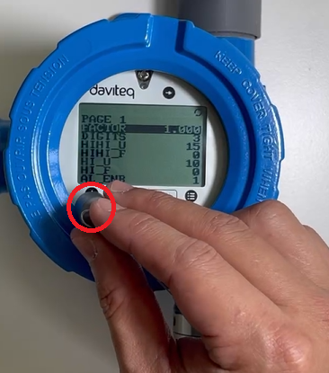
Method 2: Configuring on Local display
Please refer below video of instructions for configuring on device local display
Video of WSLRW-PID configuration:
Method 3: Configuring via Offline cable.
Note: The sensor is only active for offline configuration in the first 60 since power up by battery or plugging the configuration cable.
Position of the configuration port on the device:
Open top housing, unplug screen, unscrew the two screws, and then open the cover to access the configuration port

Which Parameters are configured?
The most important configuration is Response Factor (RFs). Our PIDs are calibrated using isobutylene, but PID is a broadband detection method with a variable sensitivity to each VOC. The relative sensitivity to each compound also varies significantly with PID photon energy (10, 10.6 or 11.7 eV). It varies much less with PID design and lamp output.
Response Factors (RFs) provide an indication of the relative sensitivity of PID to specific VOCs, relative to isobutylene. The RF of a VOC is used to convert the calibrated response of the sensor with isobutylene into a concentration of the target VOC.
Example: Toluene
A PID 10.6 eV sensor is calibrated with isobutylene and found to have a sensitivity of 1 mV/ ppm
If the sensor is exposed to 100 ppm isobutylene the output will be 100 mV.
The response factor for toluene using 10.6 eV is listed as 0.56.
If the sensor is exposed to 56 ppm toluene then the displayed uncorrected concentration will be 100 ppm isobutylene. The corrected concentration would be 100 multiplied by the RF, 0.56, which gives the correct result of 56ppm toluene.
A complete list of response factors is shown in the table of the link Table of Response Factor
The volatile organic compound, or VOC, is a carbon-containing chemical, which is significantly or completely vaporized at ambient temperatures. Occasionally you will be measuring a mixture of VOCs. If the total concentration is within the linear range of the PID, then it is reasonable to assume that the concentrations are additive without interference between the different VOCs:
The correction factor for a gas mix containing PID detectable gases A, B, C... with response factors RF(A), RF(B), RF(C), in fractional proportions a:b:c is given by:
RF mix = 1/[a/RF(A) + b/RF(B) + c/RF(C)...]
Example: A gas mix to be monitored contains 1 part isopropanol to 4 parts acetone:

Therefore, the RF of the mix will be:
RF mix = 1/[(4.0 x 0.2) + (1.17 x 0.8)] = 1/(0.8 + 0.936) = 0.58
Important:
Remember that if you are measuring a combination of VOCs then accurate measurement of one of these VOCs will be difficult; without careful data analysis you will get only a RF averaged measurement. Also, note that in the volatilisation of mixtures of VOC’s of different volatility, the more volatile fraction volatilises most rapidly, and the least volatile most slowly, leading to a change in the composition of the liquid and vapour mix.100 multiplied by the RF, 0.56, which gives the correct result of 56ppm toluene.
For other configurations, please check Part G in Section 1.9 Payload Documents above.
Please check the Part D & E in Section 1.9 Payload Documents above.
Method 1: Configuration via Downlink messages
Method 2: Configuration by Offline Cable
Please download the Configuration Template File of this sensor to be used in Step 4 below.
Instructions for offline configuration of the Daviteq LoRaWAN sensors. Please follow the following steps.
Note: The sensor is only active for offline configuration in the first 60 since power up by battery or plugging the configuration cable.
1. Prepare equipment and tools
The following items must be prepared for configuration.
A PC using the Windows OS (Windows 7 or above versions). The PC installed the COM port driver of the Modbus configuration cable (if needed). The driver is at link: Modbus Configuration Cable COM port driver for PC and the instruction to install the driver at link: How to install the driver.
A Modbus configuration cable
Tools to open the plastic housing of LoRaWAN sensors (L hex key or screwdriver)
2. Download and launch Daviteq Modbus configuration software
Click the link below to download Daviteq Modbus configuration software:
https://filerun.daviteq.com/wl/?id=yDOjE5d6kqFlGNVVlMdFg19Aad6aw0Hs
After downloading the software, unzip the file named: Daviteq Modbus Configuration.zip and then copy the extracted folder to the storage drive for long-term use.
Open the folder, double click on the file Daviteq Modbus Configuration Tool Version.exe to launch the software and the software interface as below:

Note: The software only runs on Microsoft Windows OS (Windows 7 and above).
3. Connect the cable and configure the sensor
Step 1:
Connect the PC to the sensor using the configuration cable.
- Use the configuration cable (Item code: TTL-LRW-USB-01).

- Connect the USB-A plug into the USB-A socket of the PC.

Step 2:
On the configuration software, choose the relevant Port (the USB port which is the cable plugged in) and set the BaudRate: 9600, Parity: none
Step 3:
Click Connect button to connect the software to the sensor. After successful connection, the Connected status will show on the software.

Step 4:
Import the configuration template file of the sensor (as above link) to the software: click menu File/ Import New and then browse the relevant sensor template file (csv file) and click Open to import the template file.
Note: The sensor is only active for configuration for 60 seconds since plugging the configuration cable or the power supply into the sensor.
Each sensor type has its own template file. Refer to the sensor's manual to download the correct file.
Step 5:
Open the housing of the sensor and quickly plug the connector of the configuration cable into sensor's modbus configuration port as below figure. After plugging the connector, the software will read the parameter values automatically.

Plug the cable connector into sensor's modbus configuration port. This port is located at a different location, depends on the sensor type
Note: If the sensor has SKU of WSLRWEX-PPS and hardware version 1 & 2, the sensor must be powered by batteries for configuration
Step 6:
Read the current value of the parameter with Modbus Function 3
At the relevant row of the parameter, check box 3 on column Func to read the value of the parameter. The read value is shown in VALUE ON MEMMAP column.

The sensor is only active for configuration for 60 seconds since plugging the configuration cable or the power supply into the sensor. After 60 seconds, the TIME_OUT text will show on EXCEPTION column of the software.
Step 7:
Write the new setting to the parameter with Modbus Function 16
Double click on the column VALUE TO WRITE of the parameter and input the new setting value of the parameter;
Uncheck the tick on the FC column of the parameter, click on the arrow, select 16 and then check on the FC column to write a new setting to the parameter. The WRITE_OK text will show on EXCEPTION column if the software successfully writes the setting.

Repeat Step 6 to read the setting of the parameter for double-checking.
Note: For some critical parameters of the sensor, the password in "password for setting" must be written before writing the new settings to these parameters.
Only read/ write registers are allowed to write.
The sensor is only active for configuration for 60 seconds since plugging the configuration cable or the power supply into the sensor. After 60 seconds, the TIME_OUT text will show on EXCEPTION column of the software.
4. Troubleshooting
3.3 Calibration/ Validation
How to force sensor to send data for calibration/ validation (if available)
By moving the magnet key to touch contact point (down row icon) on the screen within 1 second, the LoRaWAN device can be triggered to send data to the gateway immediately. The leaf icon will appear on local display to show that the device is triggered by the magnetic key. There will be a beep sound from the buzzer meaning the data has been sent (Buzzer will be updated in the latest version) OR cycle arrow icon appear on local display

Note:
Once sending data to the gateway by magnet key, the timer of sending time interval will be reset;
The shortest time interval between the two manual triggers is 15s. if shorter than 15s, there will be no data sending.

Calibration/ Validation sensor (if available)
The Daviteq PID Gas Sensor must be connected to a reading device, it usually is a wireless transmitter like Sub-GHz, Sigfox, or LoRaWAN.
Why do we need to calibrate the gas sensor?
There are some reasons:
- The output value of a sensor is different from the other sensor. It is not the same value for all sensors after manufacturing.
- The output value of a sensor will be changed over time.
Therefore, users need to calibrate the sensor before use or in a pre-defined interval time (30 months for example).
Calibration guidelines
PID sensor naturally produces ozone in air, which over time acts to remove organic detritus from within the PID cavity. In many domestic and light industrial environments, the PID is self-cleaning. Re-calibration is then only needed to adjust for any decay in the PID lamp output on which the photoionisation measurement depends. In a fixed instrument, typically this will be every one to two months of cumulative sensor operation. However, when first deploying a PID instrument in a new environment, end users should be encouraged to bump test and re-calibrate as necessary. Since portable PID instruments are exposed to unknown environments, their calibration may be required more often.
Calibration of instruments containing PID usually demand measurements of ‘zero gas’, containing near zero concentrations of VOCs, and a span gas, used to calibrate the PID sensor in its linear range. Both gases are usually prepared with a ‘balance’ gas of artificial air, comprising ~80% nitrogen and ~20% oxygen. Do not use pure nitrogen as a balance gas as this delivers up to 20% more responsivity than air.
Appropriate end user calibration gases for the various MiniPID 2 sensors are identified below:

Zero gas of <0.1 ppm VOC is usually provided by ultrahigh purity (UHP) air. To enable frequent calibration, purified gas systems providing the same gas purity can be used. Lubricating oils in compressed air lines should be avoided as they will foul PIDs if exposed to the gas stream for extended times.
Some gases absorb UV light without causing any PID response (e.g. methane, ethane). In ambient atmospheres where these gases are present the measured concentration of target gas will be less than is present. Methane absorbs UV strongly, so for accurate measurements in methane containing atmospheres, calibrate with a calibration gas containing the expected methane concentration.
The HS sensor requires particular care in handling as identified in the technical article TA-14. Since air may contain semi-volatiles which give rise to a significant and slowly moving sensor response, calibration of a high sensitivity VOC detector must always be undertaken after burn-in using clean air. This will provide the zero point calibration reading.
How to calibrate the PID Gas sensor?
Please follow below steps to attach the calibration cap onto the sensor module and connect the sensor to standard gas cyclinder for zero calibration and span calibration
Step 1. Prepare the calibration cap

Step 2. Attach the calibration cap to the sensor head and fix the cap by turning clockwise the T head bolt

Step 3. Install the Gas regulator to the Standard Gas cylinder

Note: Please select the flow regulator with a flow rate of 2.5 LPM or 5.0 LPM.
Step 4. Attach the tube to the regulator and calibration cap

Notes: The tube length is short as possible to reduce the gas loss.
With the 2-point calibration method, the user input the Zerro value and Span value on local display and then the device will calculate the A and B factors automatically. Please find below the steps of calibration.
Step 1. Zero calibration
- Power ON the device and wait at least 90 minutes for stable measurement
- Connect 0.1 ppm Isobutylene standard gas cylinder to the device. Detail of how to implement the connection as described above
- Access ZERO CALIBRATION menu on local display and input value of 0.1 by virtual keyboard on local display without input OK by virtual key). Then open regulator slightly to supply Isobutylene standard gas of 0.1 ppm to the device and wait for 3 minutes for stable flow and measurement, then input OK on virtual keyboard to complete the zero calibration process. Please refer below video for more detail of zero calibration
Note: DON'T use Nitrogen as standard gas for zero calibration
Step 2. Span calibration
Note: Keep the sensor Power ON all the time
- Connect 10 ppm Isobutylene standard gas cylinder to the device. Detail of how to implement the connection as described above
- Access SPAN CALIBRATION menu on local display and input value of 10 by virtual keyboard on local display (without input OK by virtual key). Then open regulator slightly to supply Isobutylene standard gas of 10 ppm to the device and wait for 3 minutes for stable flow and measurement, then input OK on virtual keyboard to complete the span calibration process. Please refer below video for more detail of zero calibration
Note:
Standard gas for span calibration MUST NOT has balance gas of Nitrogen. This gas should have balance gas of air.
Above is the span calibration for 10 ppm Isobutylene standard gas. In real condition, the span calibration could be implemented by Isobutylene with other range such as 20 ppm, 30 ppm... based on availability of Isobutylene standard gas and sensor measurement range.
- After that, immediately turn OFF the valve to save the gas;
- Remove the calibration cap from the sensor;
- Place the sensor in clean air again.
Note: Always keep the sensor Power ON all the time.
The instructions of the zero calibration and span calibration in below video:
4
PRODUCT SPECIFICATIONS
4.1 Specifications
Spec
5
WARRANTY & SUPPORT
5.1 Warranty
Warranty
Below terms and conditions are applied for products manufactured and supplied by Daviteq Technologies Inc.
Free Warranty Conditions
The manufacturer undertakes to guarantee within 12 months from shipment date.
Product failed due to defects in material or workmanship.
Serial number, label, warranty stamp remains intact (not purged, detected, edited, scraped, tore, blurry, spotty, or pasted on top by certain items).
During the warranty period, if any problem of damage occurs due to technical manufacturing, please notify our Support Center for free warranty consultancy. Unauthorized treatments and modifications are not allowed.
Product failed due to the defects from the manufacturer, depending on the actual situation, Daviteq will consider replacement or repairs.
Note: One way shipping cost to the Return center shall be paid by Customers.
Paid Warranty
The warranty period has expired.
The product is not manufactured by Daviteq.
Product failed due to damage caused by disasters such as fire, flood, lightning or explosion, etc.
Product damaged during shipment.
Product damaged due to faulty installation, usage, or power supply.
Product damage caused by the customer.
Product rusted, stained by effects of the environment or due to vandalism, liquid (acids, chemicals, etc.)
Product damage is caused by unauthorized treatments and modifications.
Note: Customers will be subjected to all repairing expenses and 2-way shipping costs. If arises disagreement with the company's determining faults, both parties will have a third party inspection appraise such damage and its decision be and is the final decision.
5.2 Support
Support via Help center
If you need our support for Daviteq device's installation, configuration, test, and decode, please input support request at link: https://forms.office.com/r/XWHbYG7yy7
Our support engineer will contact you via email or the support ticket system.
If you have any questions about the product, you can search for information on our web (https://www.iot.daviteq.com/). If you can't find the right information, please register an account and send us a request at link Contact us | Daviteq Technologies . We will respond within 24 hours.