
Only available for Logged-in member. Please login or register to access this information.Or use the Temporary User that we have provided to you via email.
expiry time

Item codes | FW Released Date | Changes Information |
|---|---|---|
WSSFC-GCB-CH4-01;WSSFC-GCB-C3H8-01;WSSFC-GCB-CO-500;WSSFC-GCB-H2S-100;WSSFC-GCB-H2-1K;WSSFC-GCB-NH3-100;WSSFC-GCB-CL2-20 | 05/07/2024 | Initial Version |
1
QUICK INSTALLATION GUIDE
1.1 Introduction
WSSFC-GCB is a Sigfox-ready sensor designed to measure flammable or toxic gas concentrations. It features high-performance, ultra-low-power gas sensing technology to accurately detect specific gas concentrations in the air. Additionally, the sensor includes a built-in siren for local alarm notifications and a button for local alarm acknowledgment. Its ultra-low-power design and smart firmware enable the sensor to operate on a single battery for 5-10 years. It supports Sigfox zones RC1, RC2, RC3c, RC4, RC5, RC6, and RC7, making it versatile for global use. The sensor is ideal for monitoring gas concentrations in industrial or commercial buildings in the areas of kitchens, parking garages, boiler rooms, laboratories, basements, HVAC rooms, utility rooms, industrial workspaces and more.
How the sensor connect to system?

System components:
The end nodes are Sigfox-Ready Sensors or Actuators;
The Sigfox Base Stations (installed and operated by Sigfox Operator);
The Sigfox Back-End (Operated by Sigfox Company);
The Application Server is the destination software users want to utilize the data from/to Sigfox-Ready sensors/ actuators.
How do you set up the Sigfox-Ready device and get its data to the Application Software? Please follow these steps:
Contact the local Sigfox Operator to sign a Data plan contract. You will be provided an account;
Log in to the Sigfox Back-end by your own account then add the Sigfox-Ready Devices. Please follow the guidelines of Sigfox back-end;
Configure the callback or data forwarding from the Sigfox Back-end to the Application Software. Please follow the guidelines of Sigfox back-end;
Once the payload is on the Application server, decode data from Payload. Please check Section 1.9 for the Payload document.
1.2 Application Notes
For Applications
Indoor Air Quality Monitor, Gas Analyzing, Warehouse Monitoring, Gas Leakage Detection
Notes
Select the suitable sensor range to get the highest accuracy vs. sensor life. Please consult our engineers.
Lifetime is 7 years for NDIR sensors, depending on sensor type and actual operating conditions.
Calibration cycles are about 30 months for the NDIR sensor, depending on actual operating conditions.
Check carefully the working temperature and humidity of the application.
1.3 When does device send Uplink messages?
The device will send uplink messages in the following cases:
Case 1: After power-up in the 60s, the device will send the first message called START_UP. The payload will tell the user the HW version, FW version, and current configuration of the device.
Case 2: Then, in every interval time (pre-configured), for example, 30 minutes, it will send the message called CYCLIC_DATA. The payload will tell the user the following data like measured values, battery level, and alarm status...
To change the cycle of data sending, you can change the value of the parameter: CYCLIC_DATA_PERIOD.
Case 3: If ALARM_ENABLED=1, the device will send ALARM message immediately when device switches from Normal state to Alarm state. It will repeat sending ALARM messages in predefined ALARM_PERIOD time interval if the Alarm state still exist.
Case 4: During the commissioning, testing, or calibration sensor, the user can force the device to send the uplink message to get the data immediately. This message is called FORCE_DATA. The payload will provide data like raw measured value, scaled measured values, battery level, and alarm status... It can be forced by applying the magnet key on the reed switch in 1s.
Case 5: If users want to change the configuration immediately, they don't need to wait until the next cyclic data-sending message; instead, they can force the device to send a special uplink message so that the device can get the new downlink message. This uplink message is named PARAMETERS_UPDATE. It can be forced by applying the magnet key in more than 5s.
Case 6: In every interval time (pre-configured), for example, 24 hours, it will send the message called HEARTBEAT. The payload will tell the user the following data like hardware version, firmware version, current sensor configuration.
Case 7: During alarm period, if the users press the ALARM_ACKNOWLEDMENT button on the device to turn off the alarm sound/light, the device will send the ALARM_ACK uplink to inform the user's alarm acknowledgement. The uplink contains the alarm acknowledgement period (unit of second) from the time of alarm initiation to the time of pressing the button.
1.4 Default Configuration
This GCB gas sensor module has the default configuration, however, those parameters can be changed. The user can change the configuration on the wireless transmitter so that the complete sensor (transducer + wireless) delivers the proper output value. Please check the Payload document for more information.
1.5 Battery/ Power Supply
The Device uses below batteries:
Battery type: Primary battery
Battery size and Voltage: size D, 3.6 VDC
Number of batteries: 01
Recommended batteries: Saft LS33600

Battery Installation
Step 1: Open upper housing by unscrewing 1 screw and taking the housing out of the slot

Step 2: Identify the correct battery polarity

Step 3: Insert a D-battery with correct polarity

Step 4: Close the upper housing: Insert the upper housing to the slot and fixed with 1 screw.
Understanding the battery levels:
Level 3 (4 bars): battery energy is 60-99%
Level 2 (3 bars): battery energy is 30-60%
Level 1 (2 bars): battery energy is 10-30%
Level 0 (1 bar): battery energy is 0-10%
1.6 What's in the Package?

1.7 Guide for Quick Test
With the default configuration, the device can be connected quickly to the Sigfox Network by the following steps.
Step 1: Prepare the values of communication settings
Device ID: Get Devive ID on the device nameplate
Device PAC: Get Devive PAC on the device nameplate
Note: All Sigfox sensors are pre-configured with the correct RC before delivery. The settings of Device ID, Device PAC, and RC could also be read from the device memory map. Please reference Section 3.2 Sensor configuration for details.
Step 2: Add the device to the Sigfox Backend
Please refer to the below Section 1.10 for details.
Step 3: Install the batteries to the device
Please refer to Section 1.5 above for instructions on battery installation.
After installing the battery in 60 seconds, the first data packet will be sent to the Sigfox network. After receiving the first data packet, the time of another packet depends on the value of the parameter: CYCLIC_DATA_PERIOD. Additionally, you can use a magnet key to touch the magnetic switch point on the housing within 1 second to initiate force packet of the device to send data instantly and the LEDs on the housing will be lit with SKY BLUE color.
Note:
If the device is required to connect to the external power, the correct external power supply must be connected to the device power connector. Refer section 1.8 INSTALLATION for details of the power wiring
If the device is required to connect to external sensor, the connection must be implemented before power up. Refer section 1.8 INSTALLATION for details of the wiring
If device is required the calibration for correct measurement, the calibration must be implemented. Refer detail at section 3.3 Calibration/ Validation.
Step 4: Decode the payload of the receiving package
Please refer to Section 1.9 Payload Document and Configuration Tables for details of decoding the receiving packet to get the measured values.
1.8 Installation
Dimension Drawings and Installation Gallery (Photos and Videos)

Please follow the checklist below for a successful installation:
1. Have you studied the dimensions of the device as above drawings?
2. Have you tested and make sure the device have been connected successfully as Section "1.7 Guide for Quick Test" above?
3. Have the device been configured properly as per Section 3.2 below?
4. Have the device been calibrated or validated as per Section 3.3 below?
5. Then you can start to install the device at site. Please check the following Installation Notes for Sensor Part (if available) before installation.
Installation Notes for Sensor Part (if available)
Notes: If a sensor has been kept in transport containers at temperatures below zero centigrade, leave it at 10∼35℃ for not less than one hour.* if the Sensor is intended to install outdoors, please use a rain guard to protect the sensor from rain and direct sunlight. Please contact us to buy this accessory.
Place the sensor in the area to monitor the target gas concentration. Please always check the gas molecular weight v.s the air.
Do not use a damaged sensor. It must be repaired only by personnel authorized by the manufacturer.
Keep the sensor out of contact with aggressive substances, e.g., acidic environments, which can react with metals, and solvents, which may affect polymeric materials.
Diffusion holes of the sensor should be protected against the ingress of sprayed liquid or waterdrops, buy using the Splash guard or Rain guard.
The sensor is not intended to measure the target gas concentration contained in fluids.
Correct measurement is provided when the ambient temperature changes not faster than 0.6℃/ min.
Inspection and maintenance should be carried out by suitably trained personnel.
Persons, who have studied this guide, must be briefed on safety precautions when operating electrical equipment intended for use in explosive areas in due course.
When dealing with a cylinder containing a gas mixture under pressure, it is necessary to follow safety regulations.
There is no risk of pollution or negative impact on human health. The sensor does not contain any harmful substances that may be released during its normal operation.
Installation Guide for Main Device
Check the Location for the best RF Signal
Make sure the site is good enough for RF signal transmission.
Tip: To maximize the transmission distance, the ideal condition is Line-of-sight (LOS) between the Sigfox sensor and the Sigfox base station. In real life, there may be no LOS condition. However, the Sigfox sensor still communicates with the Sigfox gateway, but the distance will be reduced significantly.
DO NOT install the wireless sensor or its antenna inside a completed metallic box or housing because the RF signal can not pass through the metallic wall. The housing is made from Non-metallic materials like plastic, glass, wood, leather, concrete, and cement…is acceptable.
Mounting the Device on the Wall
Step 1: Open the rear housing by using flat head screwdriver and take the rear housing out of the slot
Step 2: Mounting rear housing of the sensor on the wall using 2 provided screws. The mounted location is 30-40 mm from the ground

Step 4: Install the top housing to the rear housing, please take note slot of the housing and fixed with 1 screw. The final installation as below

1.9 Payload Document and Configuration Tables
Please click below button for:
-
Payload decoding of Uplink messages;
-
Payload encoding of Downlink messages;
-
Configuration Tables of device.
Note:
If the content of below web payload, memory map, and sample decoder could not be copied, please install the extension of "Enable Copy Paste - E.C.P" for Microsoft Edge and for Google Chrome.
1.10 How to connect device to Back-end/ Network Server/ Coordinator
This instruction is applied to all kinds of Sigfox-Ready sensor produced by Daviteq.
Step 1: Log in to the sigfox backend website

Step 2: Click on Device

Step 3: Click New → Select a group

Step 4: Fill in the required information

Note: Some of our products may not have end product certification in time, to add the product to Backend Sigfox please follow the steps below.
Click on the text as shown below

Check the box as shown below to register as a prototype

2
MAINTENANCE
2.1 Troubleshooting
Please find below steps to identify the problems from Communication Part or Sensor Part:
* If the device cannot connect to the Gateway or System or Co-ordinator at the first time, it is the Communication Problem;
* If the device status like battery, RSSI level, data status or other communication is normal, but the measured values are not updated or wrong, it would be the problems of Sensor part;
* If the data coming to gateway, system or co-ordinator is not frequently as expected, the problem would be Communication.
Please refer below the troubleshooting guide for Communication and Sensor Part.
Troubleshooting for Communication
Troubleshooting for Sensor Part (if available)
1. The measured value is not within the expected value
The sensor is drifted over time: Re-calibrate the sensor
The sensor was in a high humidity environment (> 90% RH) for more than 03 days continuously: Place the sensor in low humidity for its recovery. It may take up to 30 days to recover. If the sensor cannot recover after 30 days, please replace the new sensor module.
2. The measured value is always zero or near zero
The sensor module was removed: Please check the sensor;
The sensor is at the end of its life: Replace the sensor module.
3. Error code list
Please refer below table for error code, priority level, and recommendations
2.2 Maintenance
Maintenance for Main device
There is no requirement for maintenance of the Hardware of this Sigfox Device except for the following:
1. The battery needs to be replaced. Please check the battery status via uplink messages;
Note: When the battery indicator shows only one bar (or 10% remaining capacity), please arrange to replace the battery with a new one as soon as possible. If not, the battery will drain completely, and the resulting chemical leakage can cause severe problems with the electronic circuit board.
2. Sensor, please refer to the maintenance section of the sensor document.
Maintenance for Sensor part (if available)
Cleaning the Filter: Approx. 6-12 months for NDIR sensors
Check and clean the filter every few months, depending on the environment. Clean the filter with warm water and soap, then use compressed air to purge it from the inside out.
Re-calibration: Approx. about 30 months for NDIR sensors
The gas sensor may be drifting over time. Please check the sensor specification to identify the interval time for the re-calibration sensor.
3
ADVANCED GUIDE
3.1 Principle of Operation
Principle of Operation for device WSSFC-GCB | FW1
Daviteq Sigfox Flammable Propane Gas (C3H8) Sensor comprises 02 parts linked internally:
• The Daviteq Sigfox wireless transmitter;
• The Daviteq Sigfox Flammable Propane Gas (C3H8) module
What are the primary output values?
• GAS CONCENTRATION: Gas concentration, scaled value , unit of %LEL, used for alarm.
GAS_CONCENTRATION= (CONSTANT_A x RAW_RAW_GAS_CONCENTRATION) + CONSTANT_B
Where CONSTANT_A, CONSTANT_B are configured in the sensor memory map. This parameter equals GAS_CONCENTRATION_X10 in the uplink payload divided by 10
• RAW GAS CONCENTRATION: Raw value of GAS_CONCENTRATION. This parameter equals RAW_GAS_CONCENTRATION in the uplink payload
• TEMPERATURE: Sensor temperature, unit of oC. This parameter equals TEMPERATURE in the uplink payload
What are the secondary output values?
Below output values are useful for device maintenance and troubleshooting.
• Battery level (%): the remaining capacity of the battery. The parameter in the payload is BATTERY_LEVEL.
• Number of consecutive Alarm: The number of consecutive alarm message. This parameter in the payload is TENTATIVE. TENTATIVE will be reset to 0 when previous message is alarm and current message is cyclic.
• Alarm: alarm status of the device. The parameter in the payload is ALARM
• Acknowledgement period : Acknowledgement period since the alarm is initiated, unit of second. If the period is greater than 65535, the ACK_PERIOD equals 65535. The alarm is acknowledged when the button on the device is pressed to turn off alarm buzzer/light. This parameter equals ACK_PERIOD in the uplink payload
• Sensor module error code: Error code of sensor module. This parameter equals SENS_MOD_ERR_CODE in the uplink payload
• Sensor error: sensor working properly or not and this parameter in the payload is HW_ERROR
• Sensor current configurations: current main settings of the sensor and this parameter in the payload is LATEST_SIGFOX_DOWNLINK
• Sensor hardware version: hardware version of the sensor and this parameter in the payload is HW_VERSION
• Sensor firmware version: firmware version of the sensor and this parameter in the payload is FW_VERSION
Principle of operation
Most of the time, the device will be in sleep mode. When the timer reaches the Measure_Period (for example, 30 minutes), it will wake up the device to start the measurement.
*** This Measure_Period will affect the energy consumption of the device.
The measurement will take a certain time to finish; it can take milliseconds or seconds to finish the measurement. This measurement time depends on sensor type, required accuracy, and other factors. Shorter measurement time, lower energy consumption, and longer battery life.
After finishing the measurement cycle, the device can read all the measured parameters.
Main parameter for alarm is GAS CONCENTRATION
If parameter ALARM_ENABLE = 1
Then the device will compare the main parameter to HiHi_Alarm_setpoint and Hi_Alarm_setpoint together with Hysteresis to define the state of the device is No_Alarm or Hi_Alarm or HiHi_Alarm.
Hysteresis value is to avoid the flickering status (Alarm/No-Alarm toggling quickly) when the measured value close to alarm threshold. This device, the hysteresis is zero (fixed value).

If value of main paramter is in Blue color area of above graph, the device is in Normal or No_Alarm state;
If value of main parameter is in Red color area, the device is in HiHi Alarm state (Alarm 2);
None of above 02 states (in Yellow color area), the device will be in Hi Alarm state (Alarm 1).
How the device send uplink message base on above 03 states?
If Device state is No_Alarm, it will check the timer to reach the Cyclic_Data_Period to send the CYCLIC_DATA uplink message;
If Device state is changed from No_Alarm to Hi Alarm or HiHi Alarm, it will send alarm message immediately.
Please check the below picture to understand the operation flow when finishing the measurement cycle:

Once the alarm happens and send the first alarm message, the device will send the next alarm message in the Alarm_Period if the device is still in Alarm states (Hi Alarm or HiHi Alarm), and TENTATIVE value will increase one unit . Please check the picture below to understand the operation flow when the Alarm timer reaches the Alarm_Period. Alarm_Period is fixed value of 10 minutes.

If parameter ALARM_ENABLE = 0
The device will check the timer to reach the Cyclic_Data_Period to send the CYCLIC_DATA uplink message.
Please check the Payload document to understand clearly uplink messages, downlink messages, meaning of parameters for configuration...
Alarm configurations
HH_ALARM_SETPOINT: Too high alarm set point (HIGHHIGH_ALARM_SETPOINT) for GAS CONCENTRATION, unit of %LEL
HIGH_ALARM_SETPOINT_FACTOR: High alarm set point (HIGH_ALARM_SETPOINT) for GAS CONCENTRATION, unit of %LEL
ALARM_ENABLE: Enable/Disable ALARM event
ALARM_PERIOD: Period of time to send ALARM event
HIGHHIGH_ALARM_SETPOINT:
*If HIHI_ALARM_FACTOR <= 7
HIGHHIGH_ALARM_SETPOINT = UNSCALED_HIHI_ALARM_SETPOINT *(10^HIHI_ALARM_FACTOR)
*If HIHI_ALARM_FACTOR >=8
HIGHHIGH_ALARM_SETPOINT = UNSCALED_HIHI_ALARM_SETPOINT / (10^(16-HIHI_ALARM_FACTOR))
HIGH_ALARM_SETPOINT:
*If HI_ALARM_FACTOR <= 7
HIGH_ALARM_SETPOINT = UNSCALED_HI_ALARM_SETPOINT * (10^HI_ALARM_FACTOR)
*If HI_ALARM_FACTOR >=8
HIGH1_ALARM_SETPOINT = UNSCALED_HI_ALARM_SETPOINT / (10^(16-HI_ALARM_FACTOR))
LEDs & buzzer descriptions
Communication LED: will lit in short time when the device is sending a uplink. The color of the LED is based on sent uplink type. Please refer section 1.9 Payload and Configuration Tables for details of color
Alarm LED & buzzer: The alarm LED will blink and buzzer will ON when alarm event is initiated. The LED color is yellow for high alarm and red for too high alarm. The alarm LED and buzzer will be OFF when the ACKNOWLEDGE button on the device is pressed.
The operation of the alarm LED and the buzzer could be checked by pressing and holding 5 seconds the ACKNOWLEDGE button then the alarm LED will blink once and the buzzer will ON once.
Principle of Operation of Sensor part (if available)
NIDR measurement technology's operation principle for CH₄, C₃H₈ sensor
When infrared radiation interacts with gas molecules, infrared light is absorbed by the gas molecules at a particular wavelength, causing vibration of the gas molecules. NDIR (Non-Dispersive Infrared) gas sensors detect a decrease in transmitted infrared light which is in proportion to the gas concentration. This transmittance, the ratio of transmitted radiation energy to incident energy, is dependent on the target gas concentration.

NDIR gas sensor consist of an infrared source, detector, optical filter, gas cell, and electronics for signal processing. A single light source, dual wavelength type gas sensor has two detectors and two optical filters of different wavelengths which are placed in front of each detector. The infrared light that is absorbed by a target gas passes through the active filter with a particular bandwidth for the detection of the target gas. The infrared light that does not interact with the target gas passes through the reference filter. The difference between transmitted light intensities in these two bandwidths is converted into gas concentration. The dual wavelength sensor ensures stable measurements for a long period of operation as the aging effects of the light source or the gas cell are automatically compensated by output signals at the reference wavelength.
Mid-infrared radiation through sample gas causes a resonance of gas molecules at their natural frequency with the infrared light in the spectrum region where the energy level of infrared is equivalent to the natural frequency of gas molecules, resulting in the absorption of infrared by gas molecules in the form of molecular vibration.
The relationship between infrared transmittance and gas concentration is expressed by the Lambert-Beer law:

Where T is transmittance, I is the intensity of light passed through sample gas and an optical filter, Io is the initial light intensity emitted from the source, ε is the molar attenuation coefficient, c is gas concentration, and d is the light path length.
Because ε of the target gas and the light pass length d are fixed with an NDIR sensor, gas concentration can be measured by measuring the transmittance within the spectrum region of the absorbed energy (wavelength) by the target gas.
The initial light intensity emitted from the light source Io is preset by calibration using zero gas which does not absorb infrared light. The initial value of the molar extinction coefficient ε is set by calibration using calibration gas of known concentration.
Default Configuration Parameters of Sensor part (if available)
This GCB gas sensor module has the default configuration, however, those parameters can be changed. The user can change the configuration on the wireless transmitter so that the complete sensor (transducer + wireless) delivers the proper output value. Please check the Payload document for more information.
3.2 Configuration
How to configure the device?
Sensor configuration can be configured in 02 methods:
Method 1: Configuring via Downlink messages, port 1 (default)
Method 2: Configuring via Offline cable
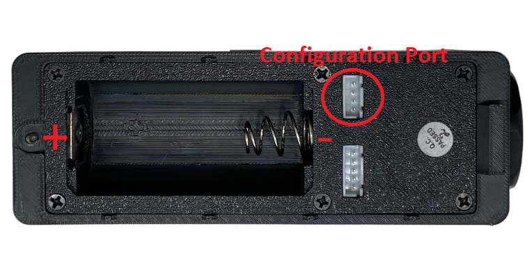
To access to the configuration port, open the upper housing by unscrewing 1 screw and take the upper housing out of the slot:
Take out the upper housing, the position of configuration port on the upper housing as below figure:
Note:
The sensor is only active for offline configuration in the first 60 since power up by battery or plugging the configuration cable.
Which Parameters are configured?
Please check Part G in Section 1.9 Payload Documents above.
Method 1: Configuration via Downlink messages
Please check the Part D & E in Section 1.9 Payload Documents above.
Method 2: Configuration by Offline Cable
Please download the Configuration Template File of this sensor to be used in Step 4 below.
Instructions for offline configuration of the Daviteq LoRaWAN sensors. Please follow the following steps.
Note: The sensor is only active for offline configuration in the first 60 since power up by battery or plugging the configuration cable.
1. Prepare equipment and tools
The following items must be prepared for configuration.
A PC using the Windows OS (Windows 7 or above versions). The PC installed the COM port driver of the Modbus configuration cable (if needed). The driver is at link: Modbus Configuration Cable COM port driver for PC and the instruction to install the driver at link: How to install the driver.
A Modbus configuration cable
Tools to open the plastic housing of LoRaWAN sensors (L hex key or screwdriver)
2. Download and launch Daviteq Modbus configuration software
Click the link below to download Daviteq Modbus configuration software:
https://filerun.daviteq.com/wl/?id=yDOjE5d6kqFlGNVVlMdFg19Aad6aw0Hs
After downloading the software, unzip the file named: Daviteq Modbus Configuration.zip and then copy the extracted folder to the storage drive for long-term use.
Open the folder, double click on the file Daviteq Modbus Configuration Tool Version.exe to launch the software and the software interface as below:

Note: The software only runs on Microsoft Windows OS (Windows 7 and above).
3. Connect the cable and configure the sensor
Step 1:
Connect the PC to the sensor using the configuration cable.
- Use the configuration cable (Item code: TTL-LRW-USB-01).

- Connect the USB-A plug into the USB-A socket of the PC.

Step 2:
On the configuration software, choose the relevant Port (the USB port which is the cable plugged in) and set the BaudRate: 9600, Parity: none
Step 3:
Click Connect button to connect the software to the sensor. After successful connection, the Connected status will show on the software.

Step 4:
Import the configuration template file of the sensor (as above link) to the software: click menu File/ Import New and then browse the relevant sensor template file (csv file) and click Open to import the template file.
Note: The sensor is only active for configuration for 60 seconds since plugging the configuration cable or the power supply into the sensor.
Each sensor type has its own template file. Refer to the sensor's manual to download the correct file.
Step 5:
Open the housing of the sensor and quickly plug the connector of the configuration cable into sensor's modbus configuration port as below figure. After plugging the connector, the software will read the parameter values automatically.

Plug the cable connector into sensor's modbus configuration port. This port is located at a different location, depends on the sensor type.
Note: If the sensor has SKU of WSSFCEX-PPS and hardware version 1 &2, the sensor must be powered by batteries for configuration
Step 6:
Read the current value of the parameter with Modbus Function 3
At the relevant row of the parameter, check box 3 on column Func to read the value of the parameter. The read value is shown in VALUE ON MEMMAP column.

The sensor is only active for configuration for 60 seconds since plugging the configuration cable or the power supply into the sensor. After 60 seconds, the TIME_OUT text will show on EXCEPTION column of the software.
Step 7:
Write the new setting to the parameter with Modbus Function 16
Double click on the column VALUE TO WRITE of the parameter and input the new setting value of the parameter;
Uncheck the tick on the FC column of the parameter, click on the arrow, select 16 and then check on the FC column to write a new setting to the parameter. The WRITE_OK text will show on EXCEPTION column if the software successfully writes the setting.

Repeat Step 6 to read the setting of the parameter for double-checking.
Note: For some critical parameters of the sensor, the password in "password for setting" must be written before writing the new settings to these parameters.
Only read/ write registers are allowed to write.
The sensor is only active for configuration for 60 seconds since plugging the configuration cable or the power supply into the sensor. After 60 seconds, the TIME_OUT text will show on EXCEPTION column of the software.
4. Troubleshooting
3.3 Calibration/ Validation
How to force sensor to send data for calibration/ validation (if available)
Using the magnet key, the device can be triggered to send data to the Base Station immediately. Touch the magnet key to magnetic point on the device housing within 1 second to trigger sending force message.


Note:
Upon transmitting the data to the base station using the magnetic key, the timer for the transmission time interval will be reset.
The minimum time interval between two manual triggers is 15 seconds. If the interval is less than 15 seconds, data transmission will not occur.
Calibration/ Validation sensor (if available)
The Daviteq GCB Gas Sensor must be connected to a reading device, it usually is a wireless transmitter like Sub-GHz, Sigfox, or LoRaWAN.
Why do we need to calibrate the gas sensor?
There are some reasons:
- The output value of a sensor is different from the other sensor. It is not the same value for all sensors after manufacturing.
- The output value of a sensor will be changed over time.
Therefore, users need to calibrate the sensor before use or in a pre-defined interval time (30 months for example).
How to calibrate the GCB Flammable Gas sensor?
Please follow steps for Instruction to attach the calibration cap onto the sensor module to get Zero or Span values:
Step 1. Remove the sensor filter by pulling the filter by hand. The filter is attached to the sensor by 2 small magnetic points

Step 2. Prepare calibration cap

Step 3. Attach the calibration cap to the sensor head

Step 4. Installed the Regulator to the Gas cylinder

Step 5. Attach the tube to the regulator and calibration cap
Please select the flow regulator with a flow rate of 2.5 LPM or 5.0 LPM.

With the 2-point calibration method, the user can define the A and B factors. Please find below the steps of calibration.
Step 1. Get the Zero value.
- Power ON the device;
- Place the device in a clean-air environment (the target value is nearly zero) at a temperature from 20∼30℃, in at least 60 minutes.
- After 60 minutes, force the device to send data, read and record the Raw_Gas_Concentration, so now you got the Zero_value = Raw_Gas_Concentration value.
Recommendation: Record many Raw_Gas_Concentration values at least 10 minutes apart (10 values). Zero value is the average of the recorded Raw values.
Note: The Raw_Gas_Concentration values can be positive or negative;
Step 2. Get the Span value
Note: Keep the sensor Power ON all the time
- Use the standard gas cylinder with a known concentration (for example C3H8 Air 1.05% volume is equivalent to 50% LEL ) to supply the gas to the sensor;
- Use the calibration cap as above pictures to attach to the sensor and connect the tubing to the gas cylinder;
- Open the valve on the Cylinder slowly and make sure the gas has reached the sensor. The flow regulator should be 2.5 LPM or 5.0 LPM.
Notes: The tube length is short as possible to reduce the gas loss.
- Press a timer to start counting the time;
- After 2 minutes, force the device to send data once every minute, and stop forcing at 5 minutes;
- The highest Raw_Gas_Concentration is the Span value.
Note: Just get one value for Span.
- After that, immediately turn OFF the valve to save the gas;
- Remove the calibration cap from the sensor;
- Place the sensor in clean air again.
Note: Always keep the sensor Power ON all the time.
Step 3. Calculate the new A and B
The calculation of new A, B value based on basic linear formula:
y = A * x + B
Where:
A, B is calibration coefficients
x is the sensor process value (example gas level in ppm) read on reading device such as on application server/network server, on offline tool. The process value is the RAW_VALUE in the payload
y is the correct value. y is the value of standard gas/standard condition
Which condition of Zero value: y₀ = A * x₀ + B
Which condition of Span value: yₛ = A * xₛ+ B
From the two formulas, the calculation of A, B as below
A = (y₀ - yₛ) / (x₀ - xₛ)
B = (yₛ * x₀ - y₀ * xₛ) / (x₀ - xₛ)
Example of A, B calculation for LoraWAN Ammonia Gas sensor (item code WSLRW-G4-NH3-100-01):
* With condition of clean-air environment at a temperature from 20∼30℃, there is no ammonia gas (y₀ = 0); while the NH₃ level on reading device (RAW_VALUE in the payload) is -0.25 (x₀ = -0.25)
* When the sensor is connected to standard gas cylinder having ammonia level of 25 ppm (yₛ = 25); while the NH₃ level on reading device (RAW_VALUE in the payload) is 18.66 (xₛ = 18.66)
The calculation of A, B for the Ammonia gas sensor:
A = (0 - 25) / (-0.25 - 18.66) = 1.32205
B = (yₛ * x₀ - y₀ * xₛ) / (x₀ - xₛ) = (25 * (-0.25) - 0 * 18.66) / (-0.25 - 18.66) = 0.33051
The factory default A = 1 and default B = 0
The RAW_VALUE in the payload is used for calibration
Step 4. Configure the new A and B into the device
- User can use the off-line tool or downlink to write the values of A and B;
- Writing the new A and B successfully meant you had done the calibration process.
4
PRODUCT SPECIFICATIONS
4.1 Specifications
Spec
5
WARRANTY & SUPPORT
5.1 Warranty
Warranty
Below terms and conditions are applied for products manufactured and supplied by Daviteq Technologies Inc.
Free Warranty Conditions
The manufacturer undertakes to guarantee within 12 months from shipment date.
Product failed due to defects in material or workmanship.
Serial number, label, warranty stamp remains intact (not purged, detected, edited, scraped, tore, blurry, spotty, or pasted on top by certain items).
During the warranty period, if any problem of damage occurs due to technical manufacturing, please notify our Support Center for free warranty consultancy. Unauthorized treatments and modifications are not allowed.
Product failed due to the defects from the manufacturer, depending on the actual situation, Daviteq will consider replacement or repairs.
Note: One way shipping cost to the Return center shall be paid by Customers.
Paid Warranty
The warranty period has expired.
The product is not manufactured by Daviteq.
Product failed due to damage caused by disasters such as fire, flood, lightning or explosion, etc.
Product damaged during shipment.
Product damaged due to faulty installation, usage, or power supply.
Product damage caused by the customer.
Product rusted, stained by effects of the environment or due to vandalism, liquid (acids, chemicals, etc.)
Product damage is caused by unauthorized treatments and modifications.
Note: Customers will be subjected to all repairing expenses and 2-way shipping costs. If arises disagreement with the company's determining faults, both parties will have a third party inspection appraise such damage and its decision be and is the final decision.
5.2 Support
Support via Help center
If you need our support for Daviteq device's installation, configuration, test, and decode, please input support request at link: https://forms.office.com/r/XWHbYG7yy7
Our support engineer will contact you via email or the support ticket system.
If you have any questions about the product, you can search for information on our web (https://www.iot.daviteq.com/). If you can't find the right information, please register an account and send us a request at link Contact us | Daviteq Technologies . We will respond within 24 hours.